 3D Print Settings:
 Some Photos of Process & Product:
Design
Process
My initial light innered was a mini LED flashlight we made in HCDE 539 last quarter. Using my calipers, I measured its dimensions and used the measurements to create the lampshade. Step 2: Sketch idea for lamp shade
To execute my idea, I first sketched out how I pictured the cube shaped lamp and the corresponding connector pieces. I cut up thin cardboard to physically visualize if my connector idea would work. Through the sketches and physical visualization, I had a good feeling about my design.
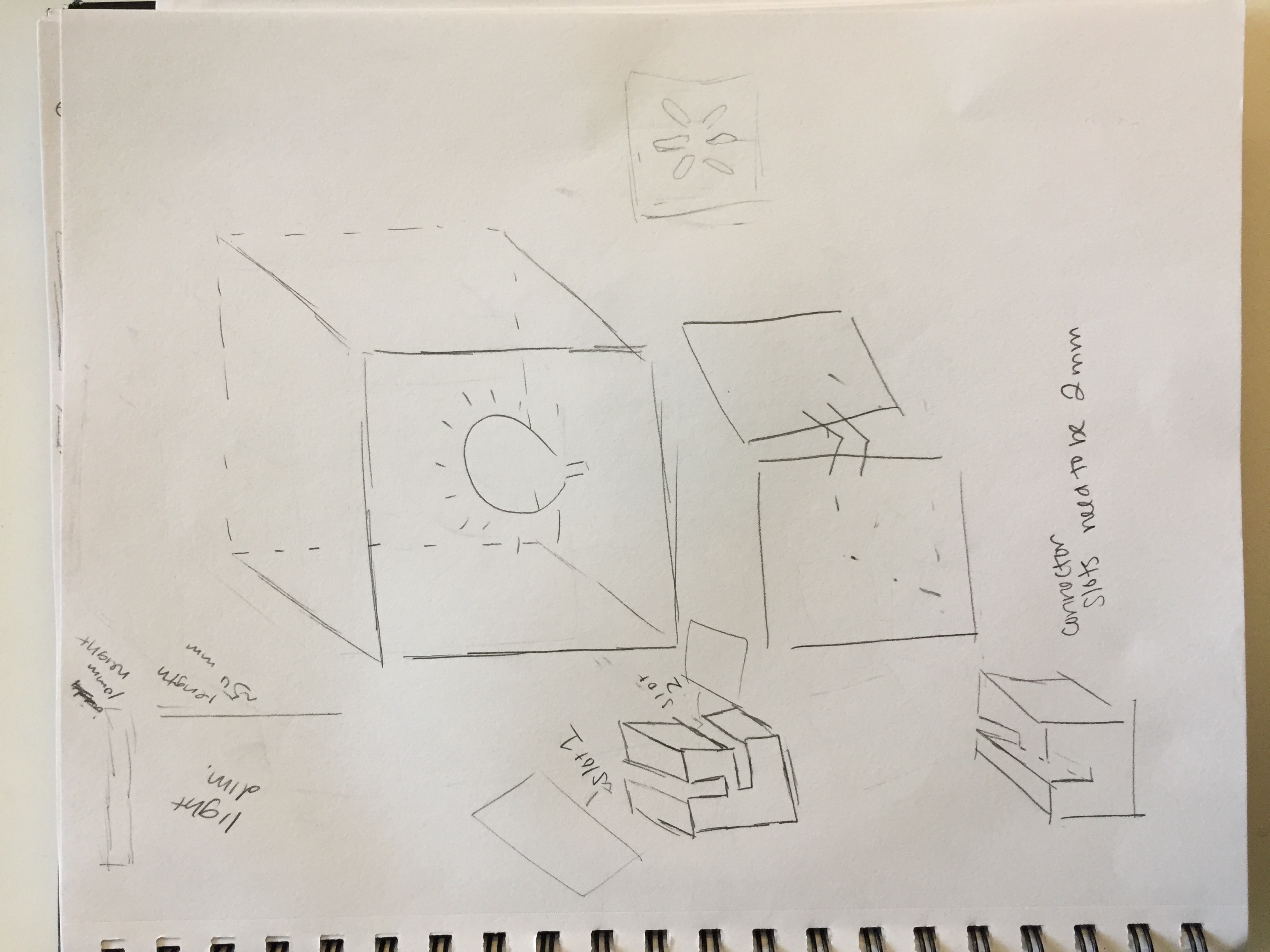
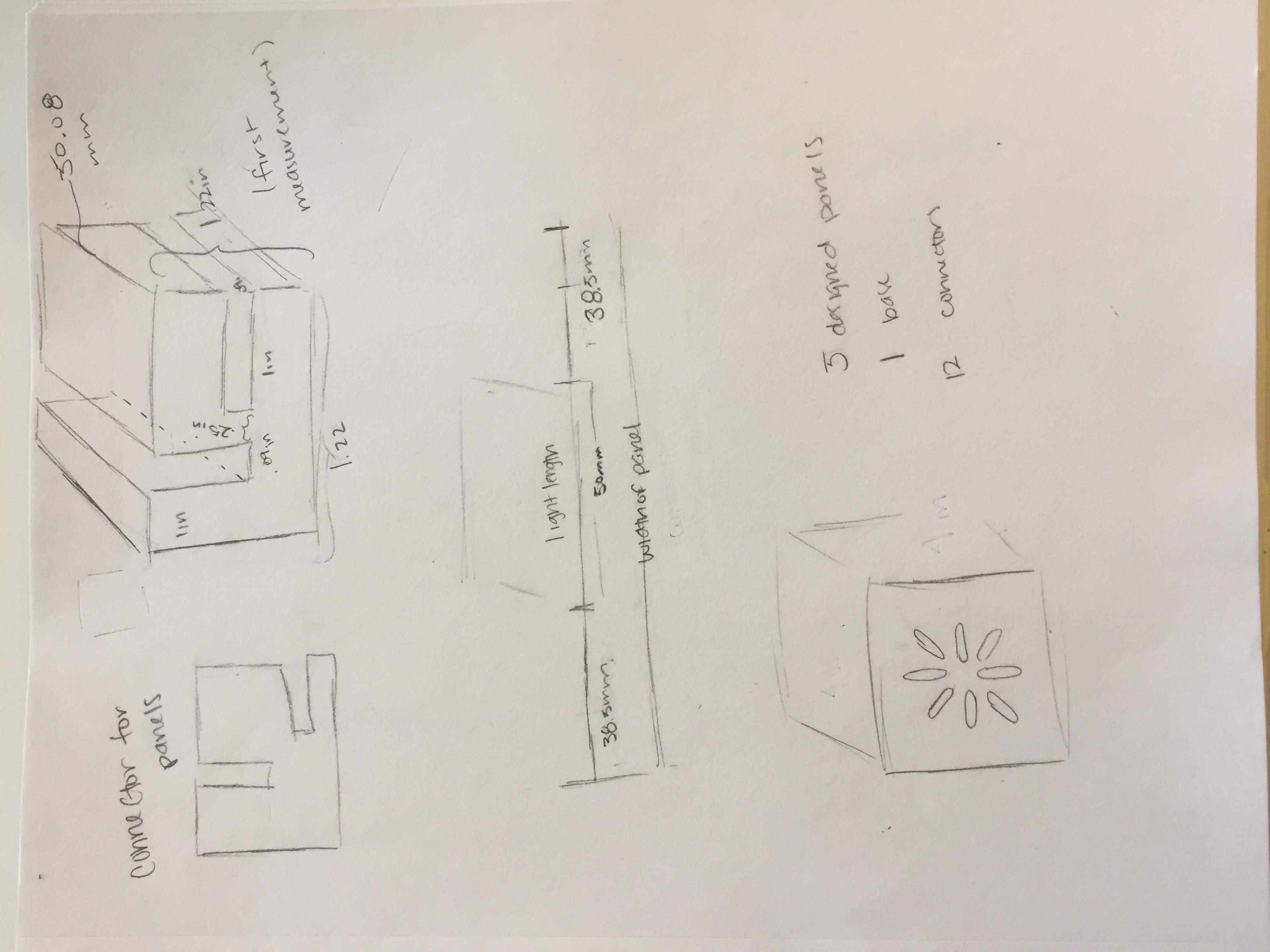
Sketches for Lamp Idea
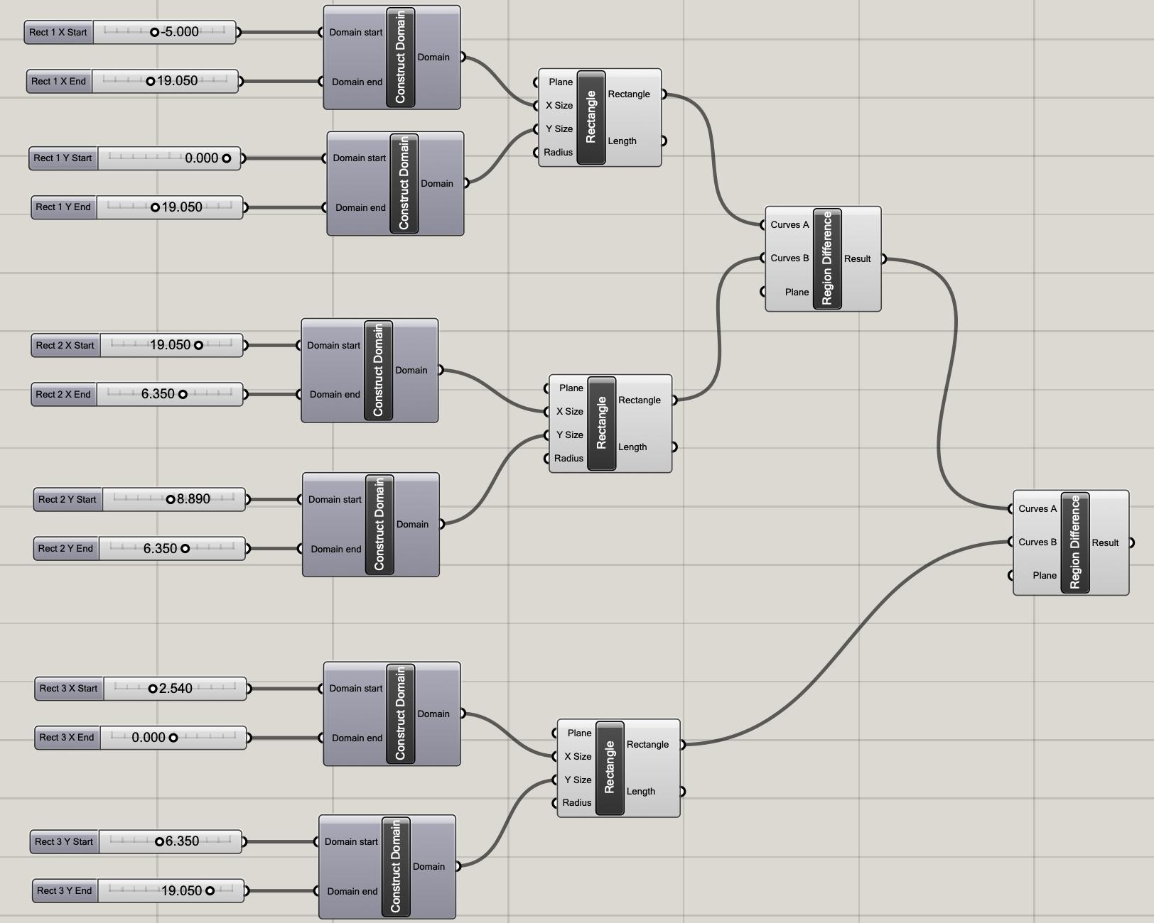
Since the connectors were going to be 3D printed, I used Rhino & Grasshopper to create the pieces. I chose to use Grasshopper because of the parameterization features. Just in case my measurements were off, I'd be able to easily adjust them using the number sliders. I did struggle a little bit creating the 3D figure of my connector. I tried using the box tool but had issues with region difference since region difference is used on surfaces, and it couldn't convert box to surface. I used Google to help me, but I had a hard time understanding some of the forums. What I ended up doing was using the demo Nadya did in class where she used 2D shapes then moved one along Z then lofted and capped it to guide me. I used the Grasshopper structure for my square shape from last week's assignment and tailored it to what I had in mind for my 2D connector shape. After I baked the 2D shape, I made a copy of it and moved the copy in the Z direction. I lofted the two shapes and capped them and ta-da! I had my 3D connector piece. Because I had never 3D printed before and was unsure how sturdy the piece would be, I made my test piece on the bigger side 1in x 1.2in x 1.5in.
Rhino Image of My First Test Piece
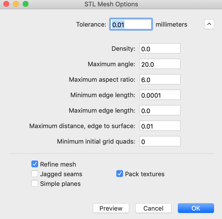
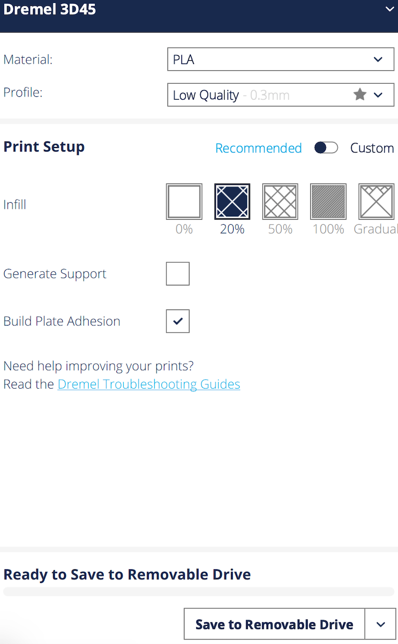
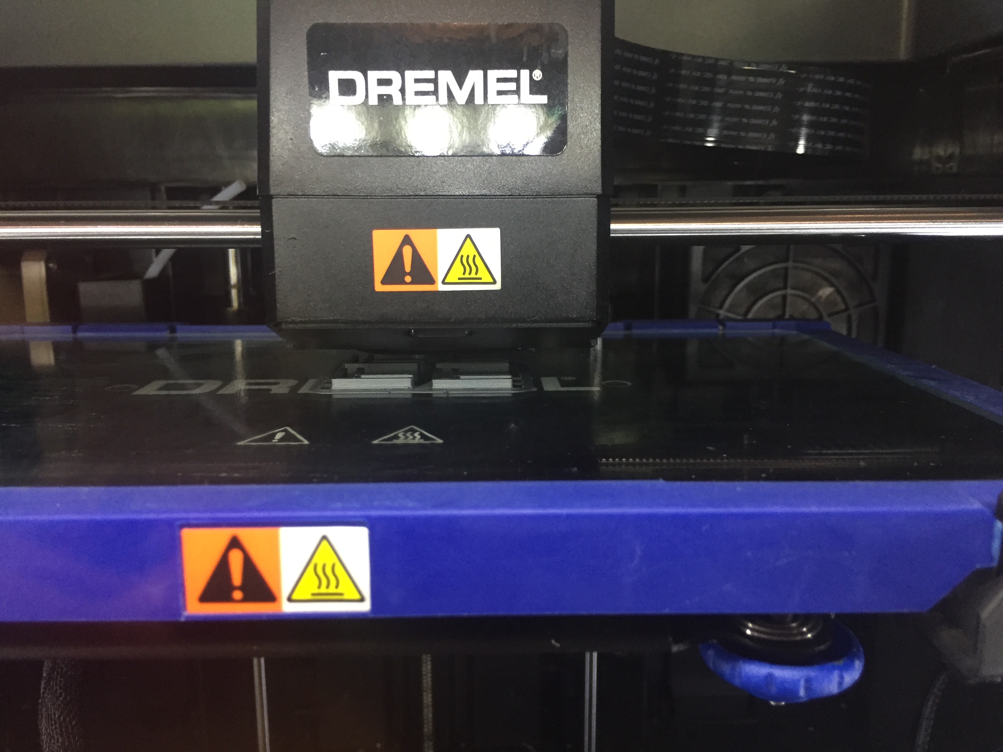
I went to office hours Thursday night to do a test print of my connector piece. Joshua gave me advice on the export settings from Rhino to STL and helped me set up the DigiLab file. I made sure there was no overhang by looking at my shape from all angles. Josh walked me through the settings like the material, the quality of the print, infill percentage, support or no support, and build plate adhesion or none. For this test print, Josh said I would be okay with no build plate adhesion (aka skirt), so I chose no. Once the settings were applied, it was time to save the file to my USB and print!
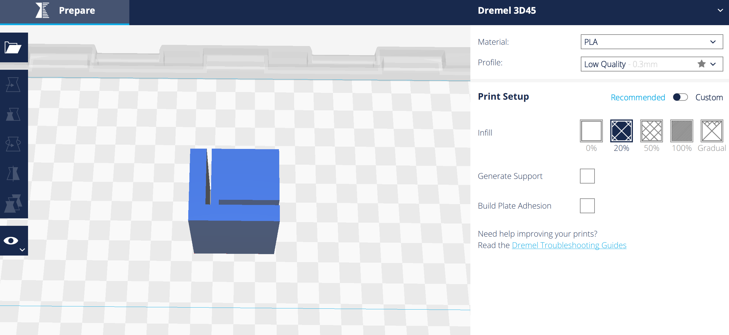
Test Print Settings
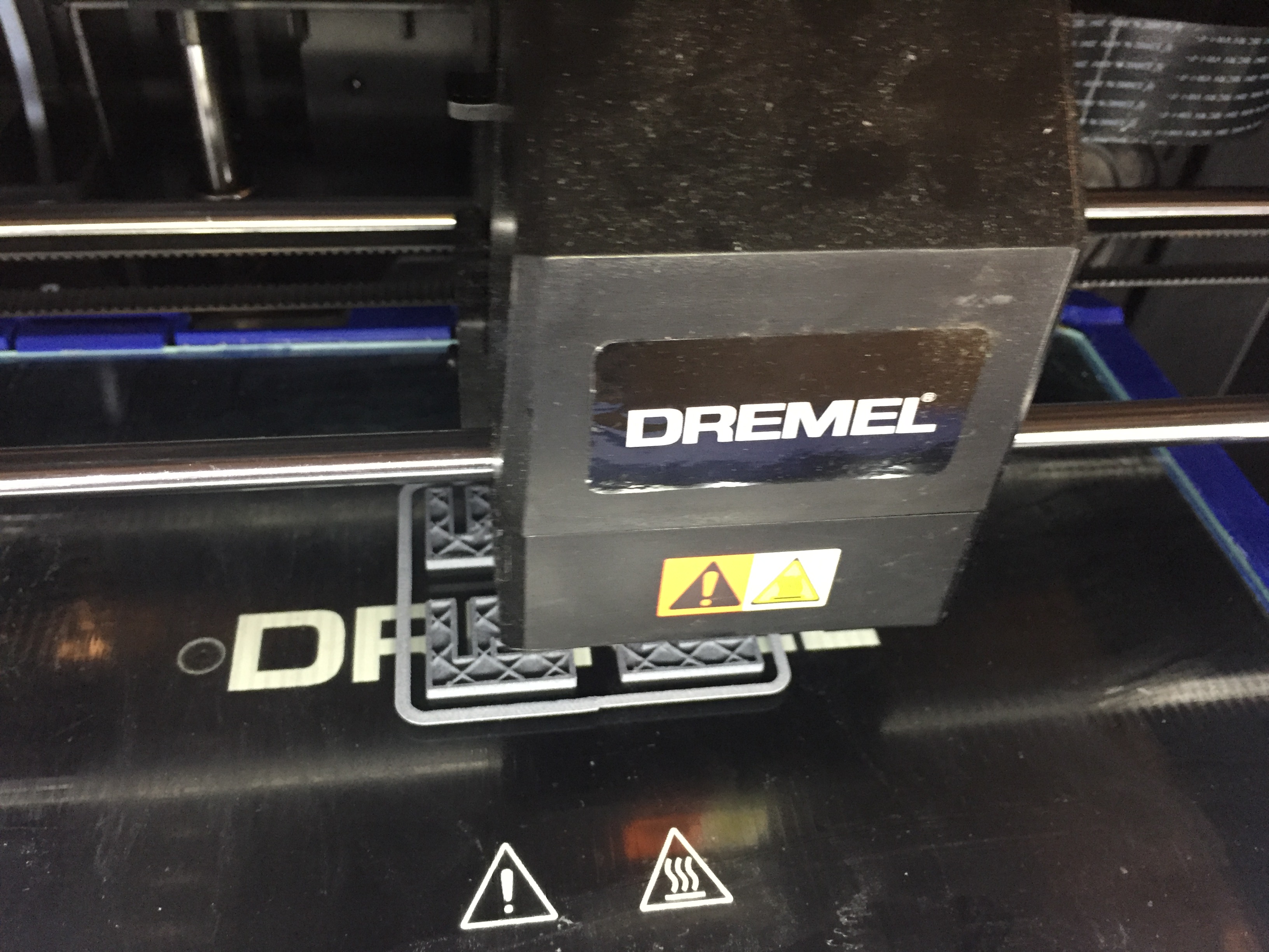
After over an hour my test print was complete, and the piece turned out fine! It was tricky getting the piece off of the glass plate. Joshua showed me the alcohol trick to help remove the piece.
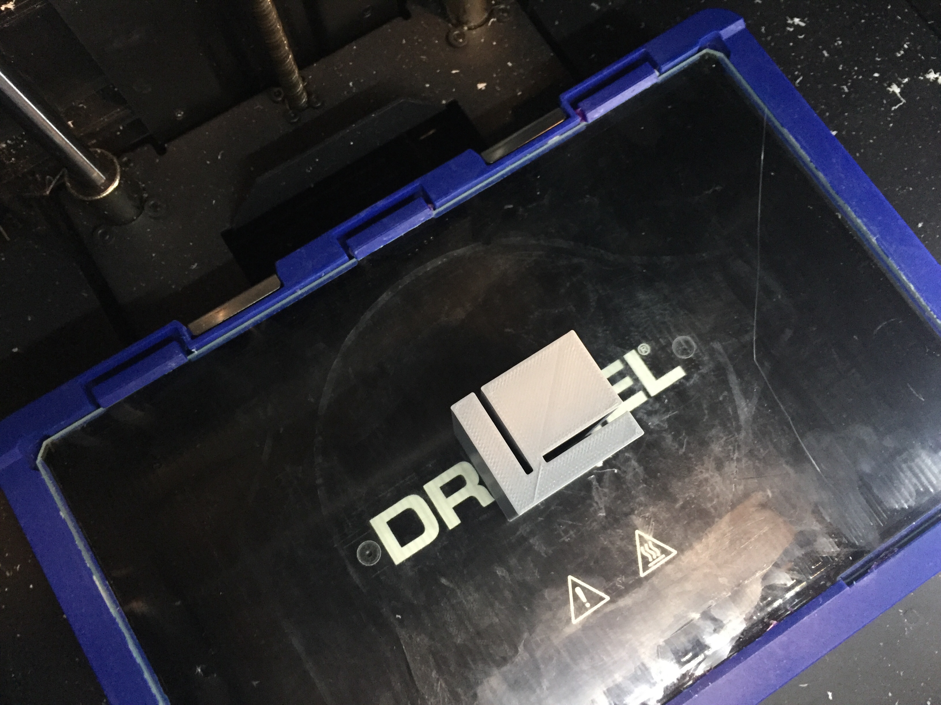
Test Print of Base Connector
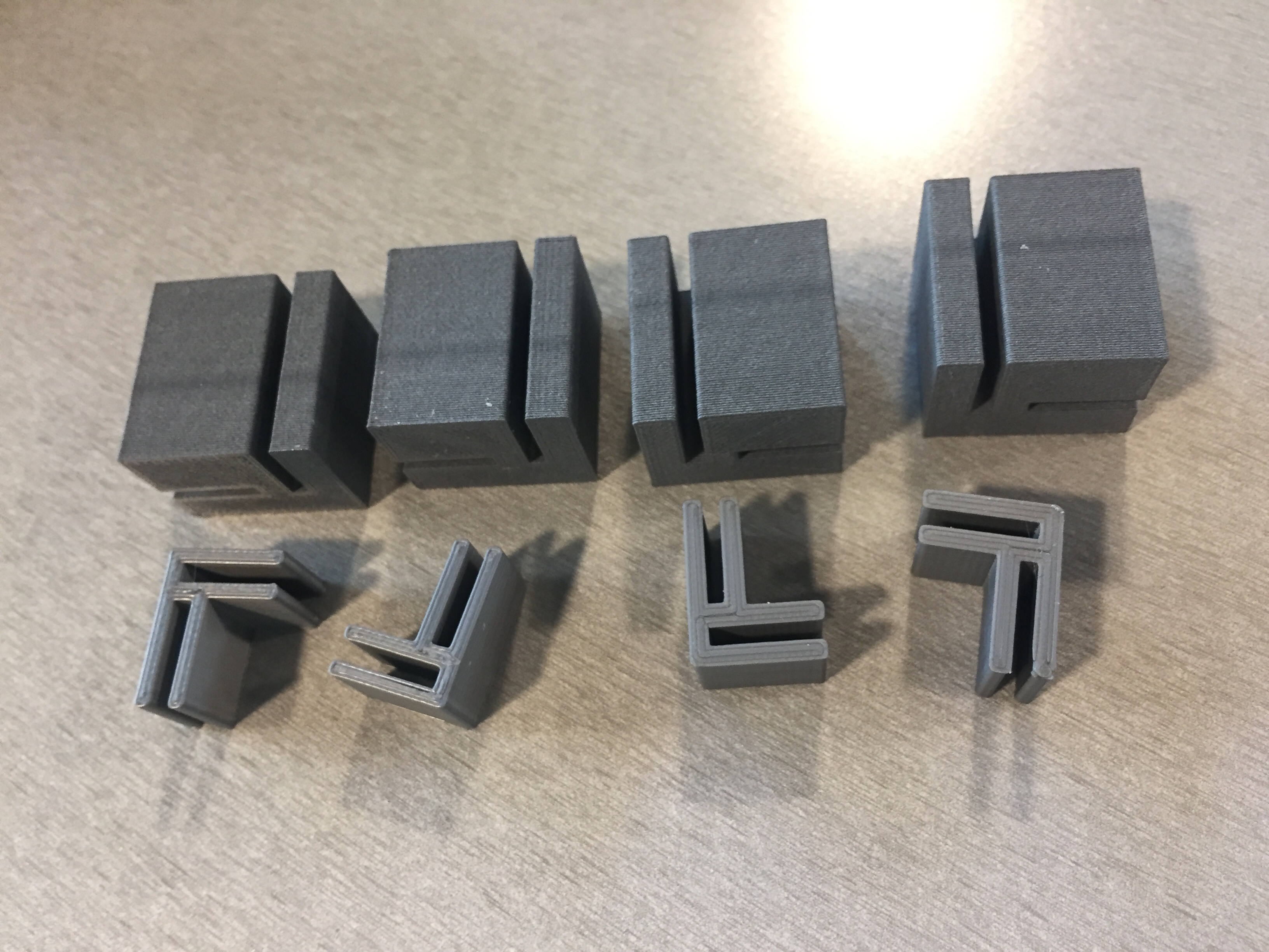
My test print was definitely sturdy because of the huge size, so I knew I could make adjustments to make the piece smaller and still be sturdy. After seeing my test print, Elizabeth gave me the suggestion to make 4 base pieces that are bigger in size so they can be sturdy and hold the lamp up while making the top connector pieces to smaller to be less weight and not make the top half of the cube fall through. Because I used Grasshopper, I easily adjusted the shape size to make it half the size of the test piece. I baked the new shape, made a copy, moved the copy in the Z direction to over half an inch and lofted and capped the shape.
Grasshopper & Rhino for the Base
DigiLab Settings
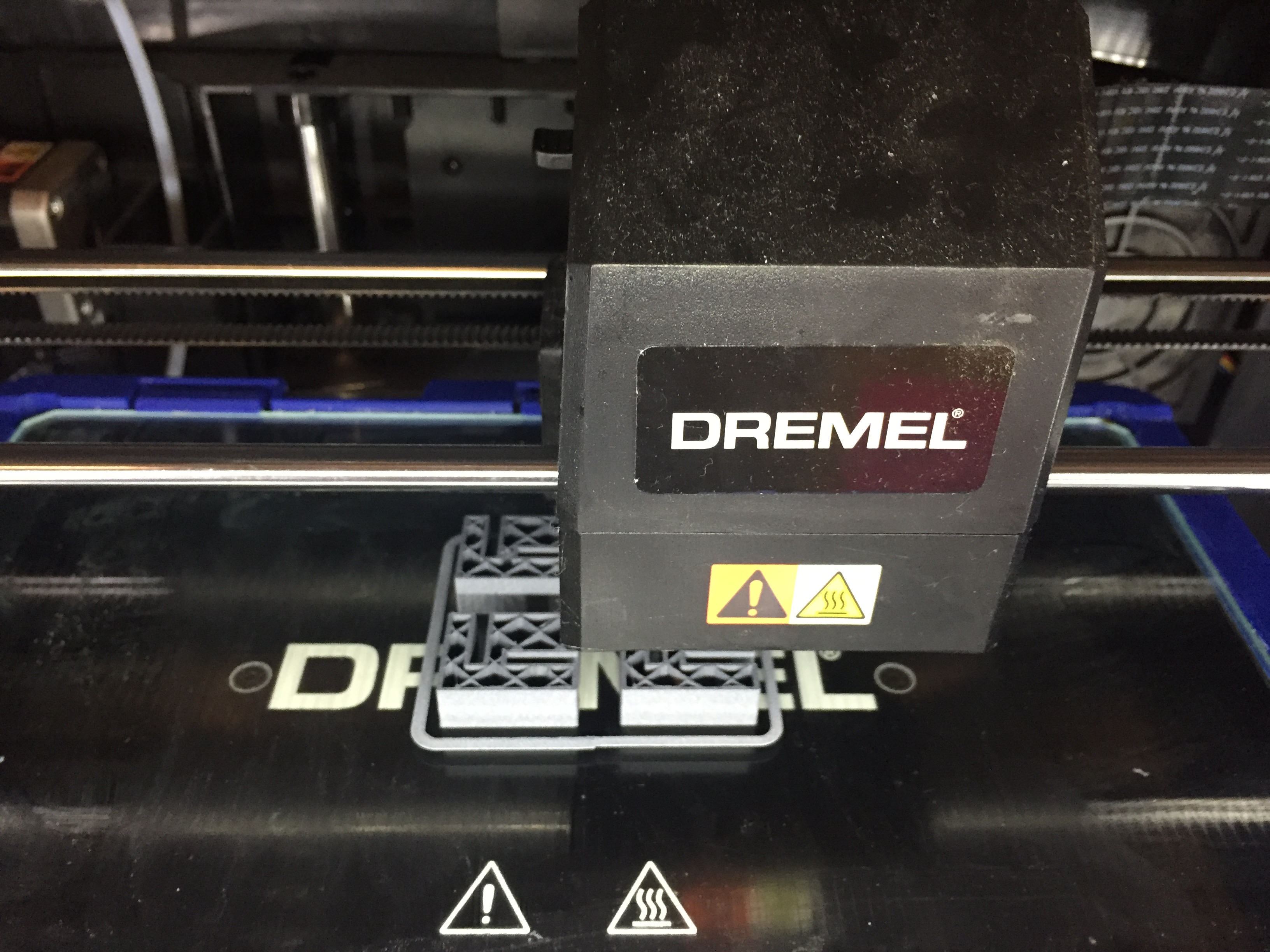
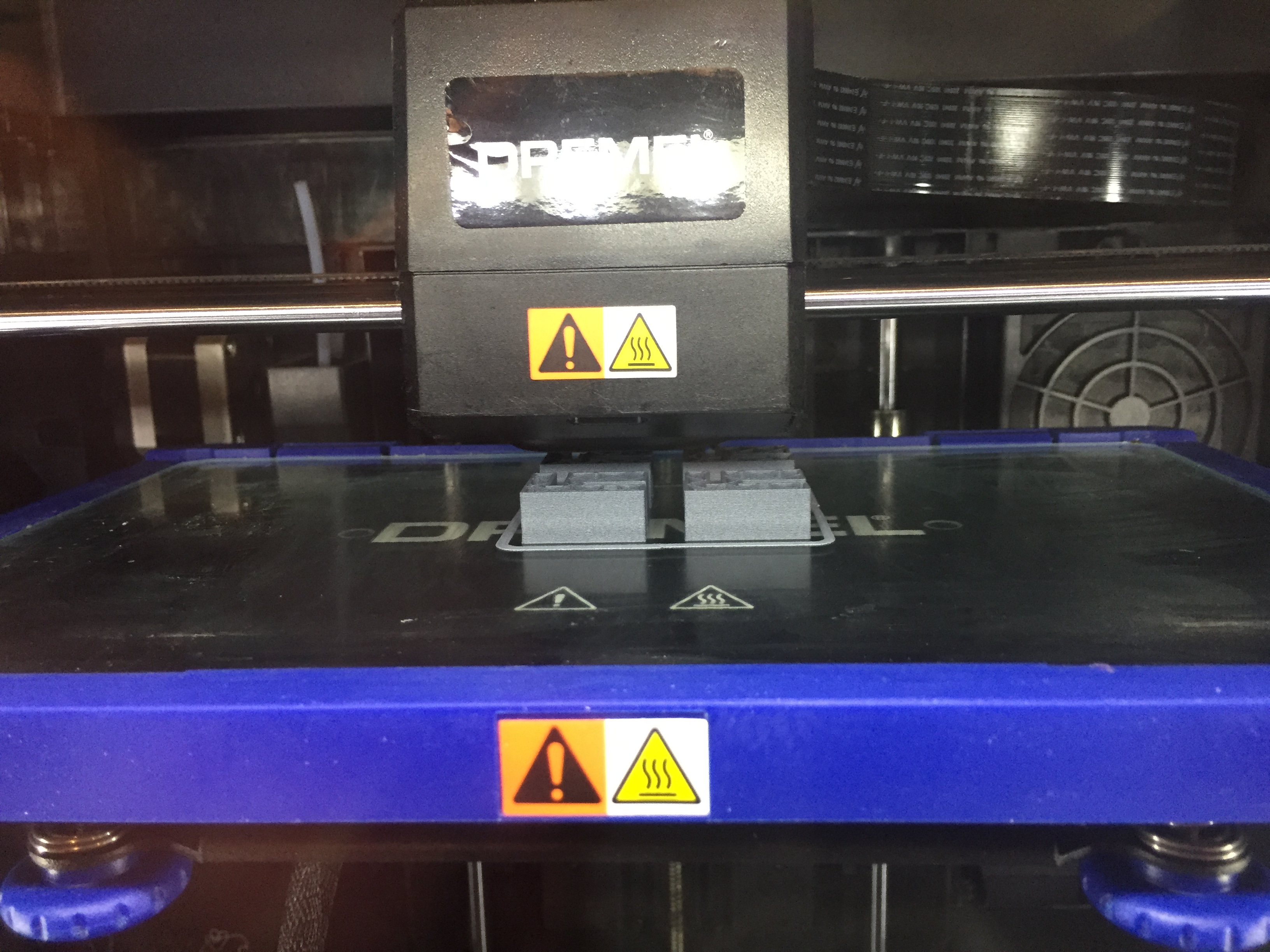
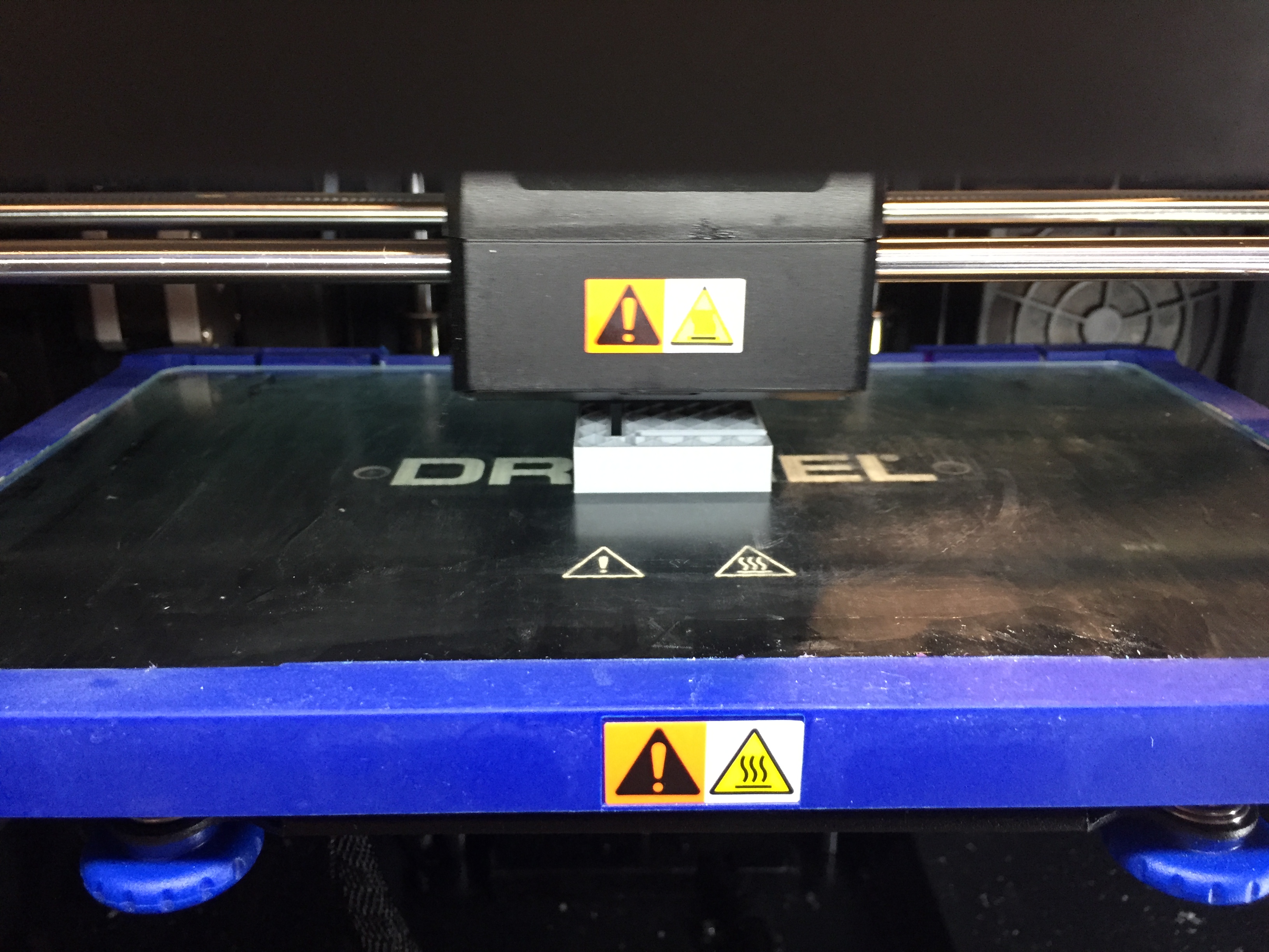
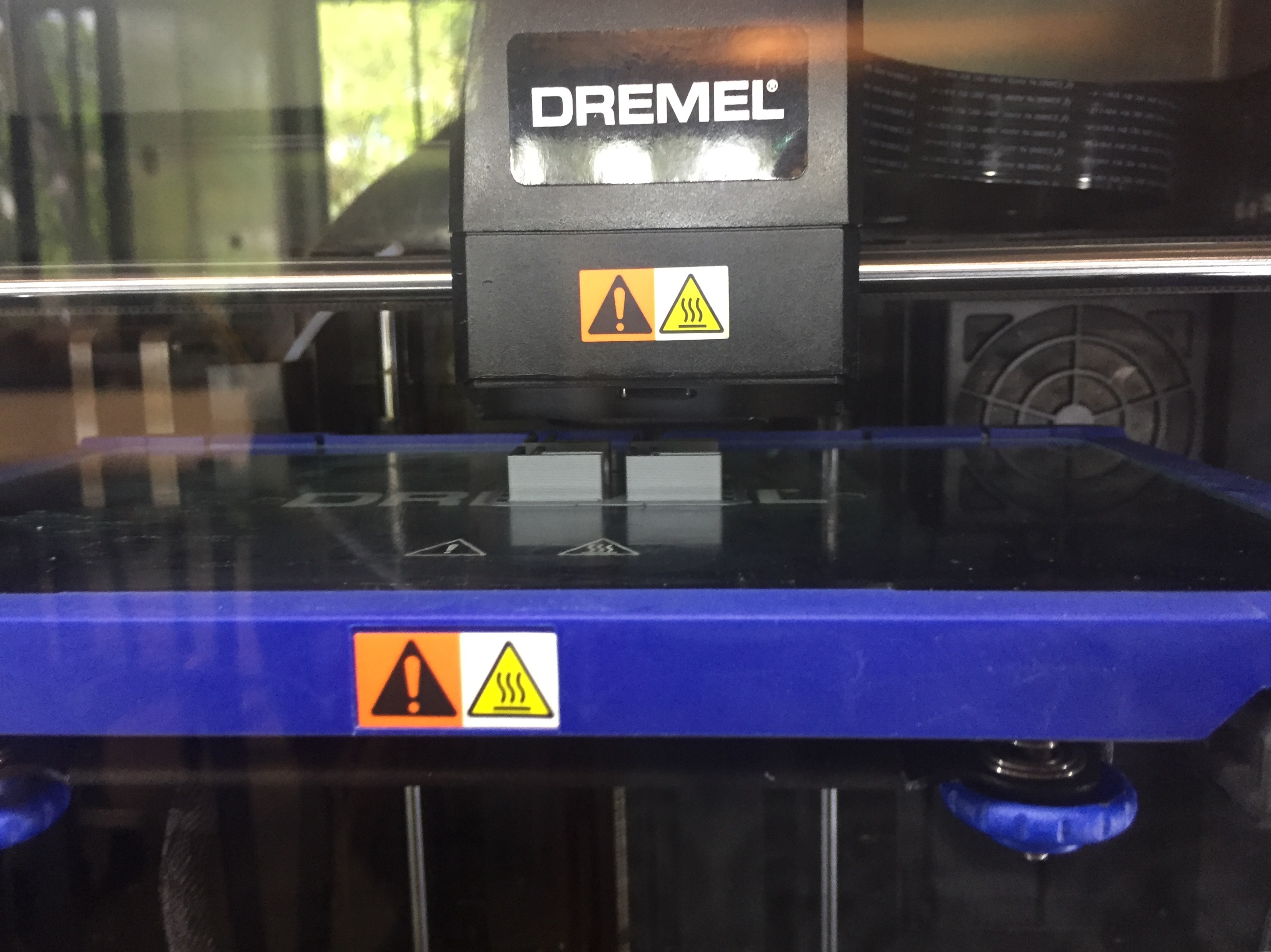
3D Printing Base Pieces
Base Connector Pieces
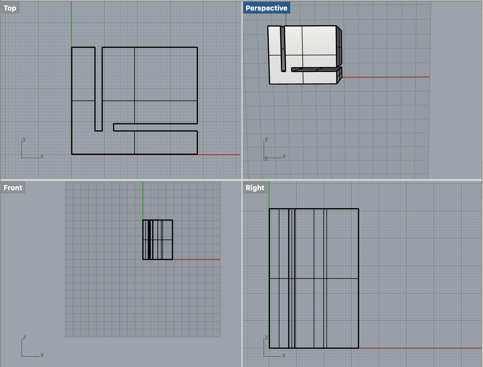
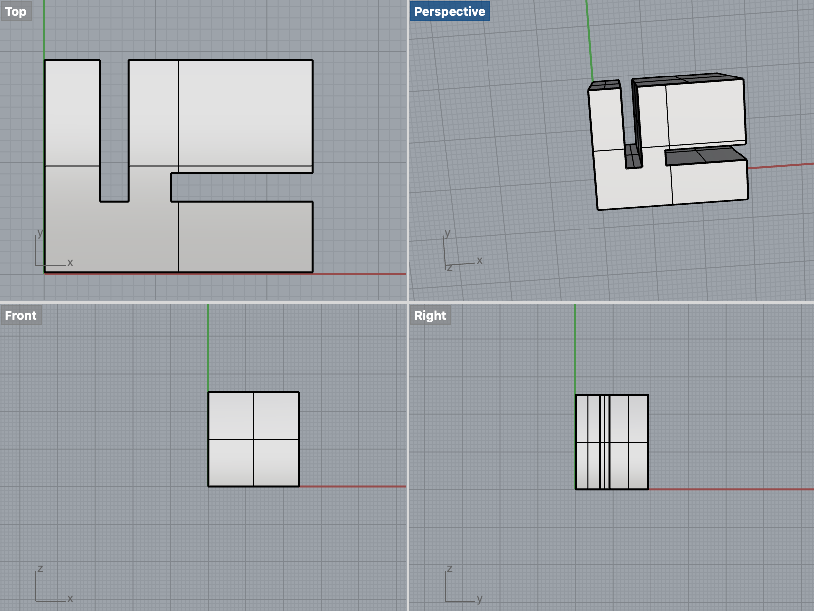
With my base connectors done, it was time to think about the top connectors. As I mentioned, Elizabeth brougth up a good point in wanting to make the connectors for the top of the panel. I chose to make the top connectors a smaller/thinner version of the base. I created a new code on Grasshopper by incorporating what I did with the base connectors with the addition of another rectangle to eliminate a giant cube from the connector to reduce its size. Once I was happy with the shape, I did the same exact process of baking, copying, moving the copy in the Z direction, lofting, and capping.
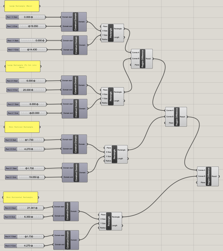
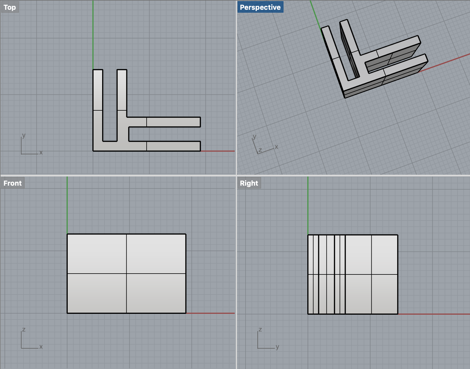
Grasshopper & Rhino for the Top Pieces
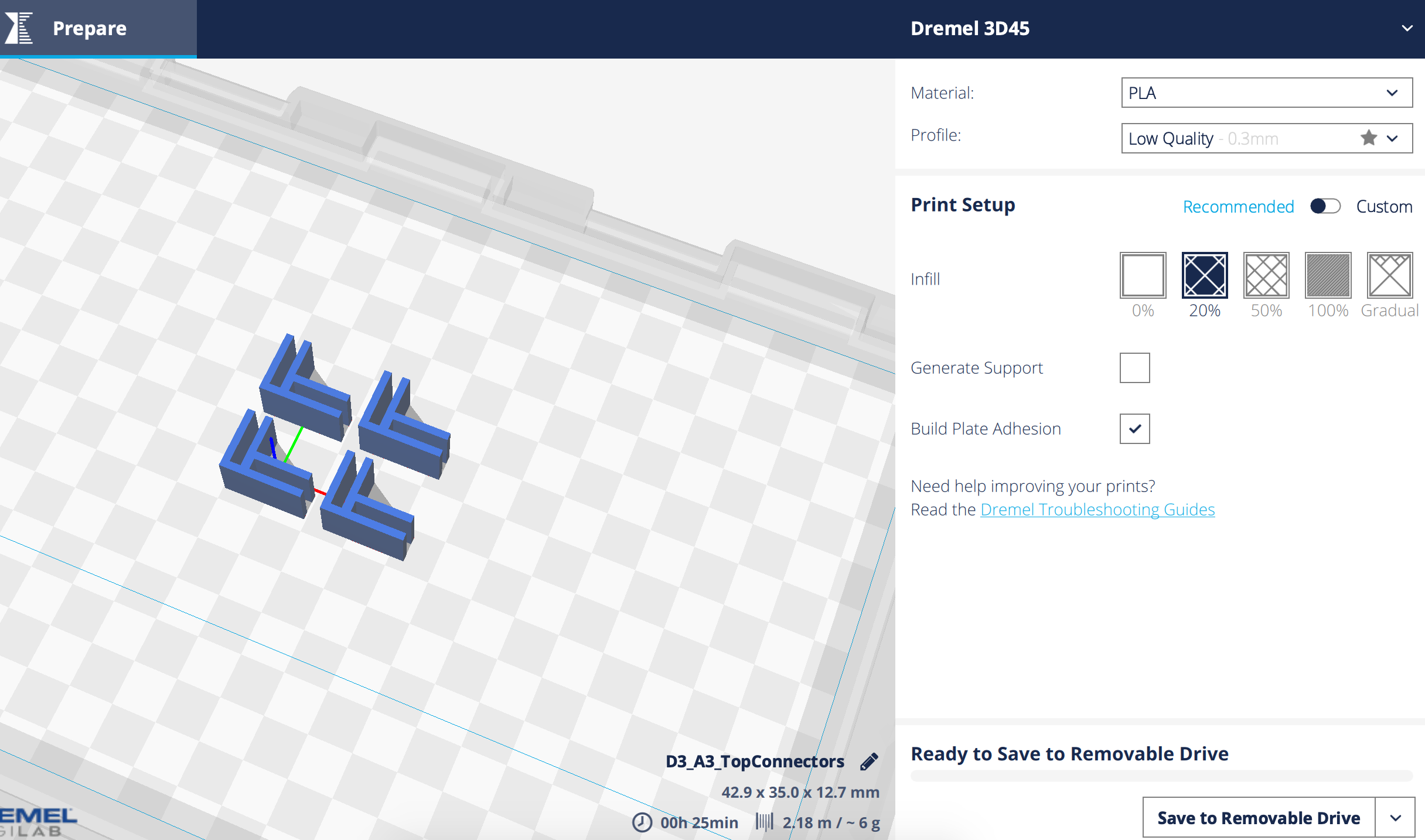
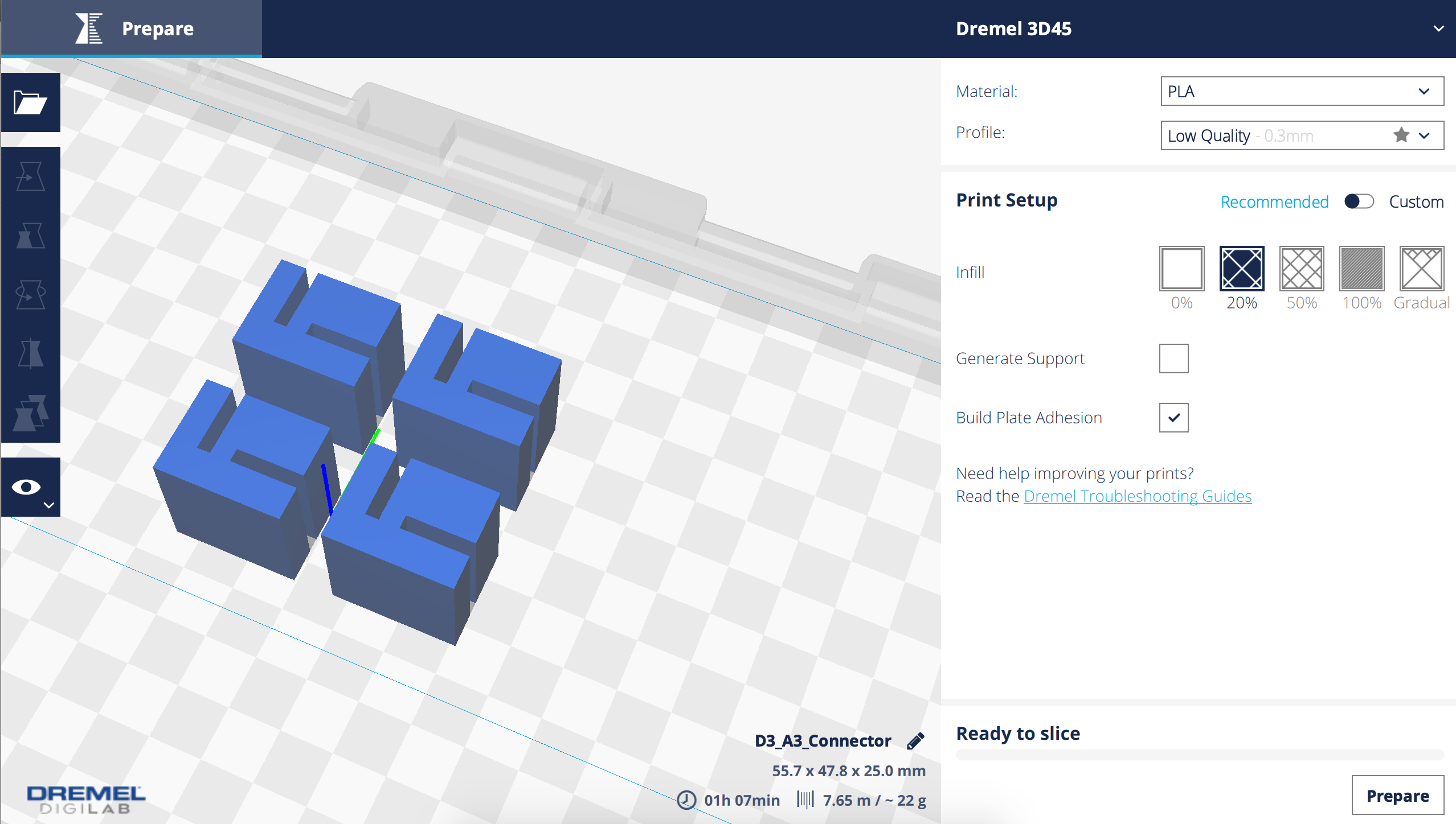
DigiLab Settings
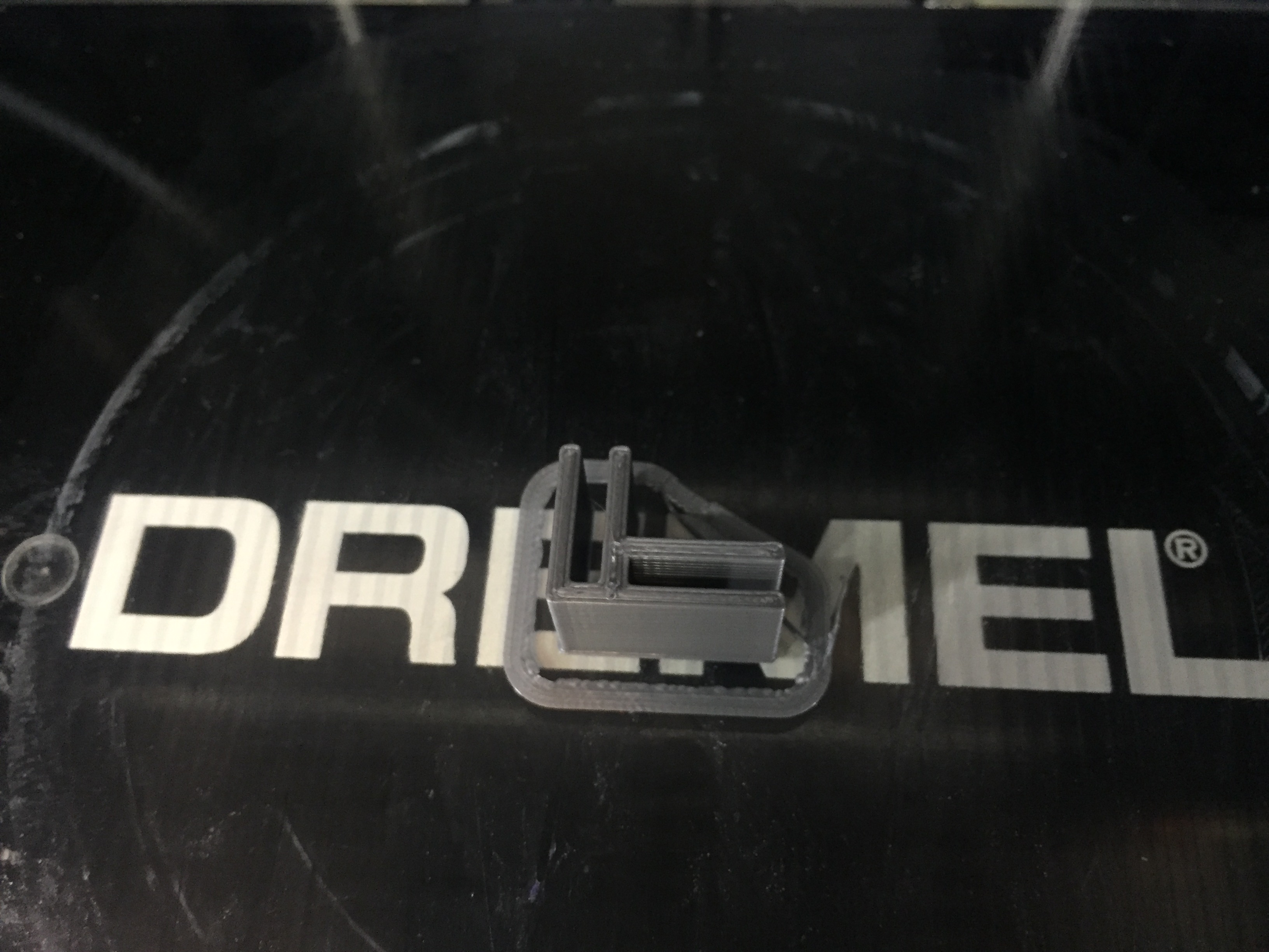
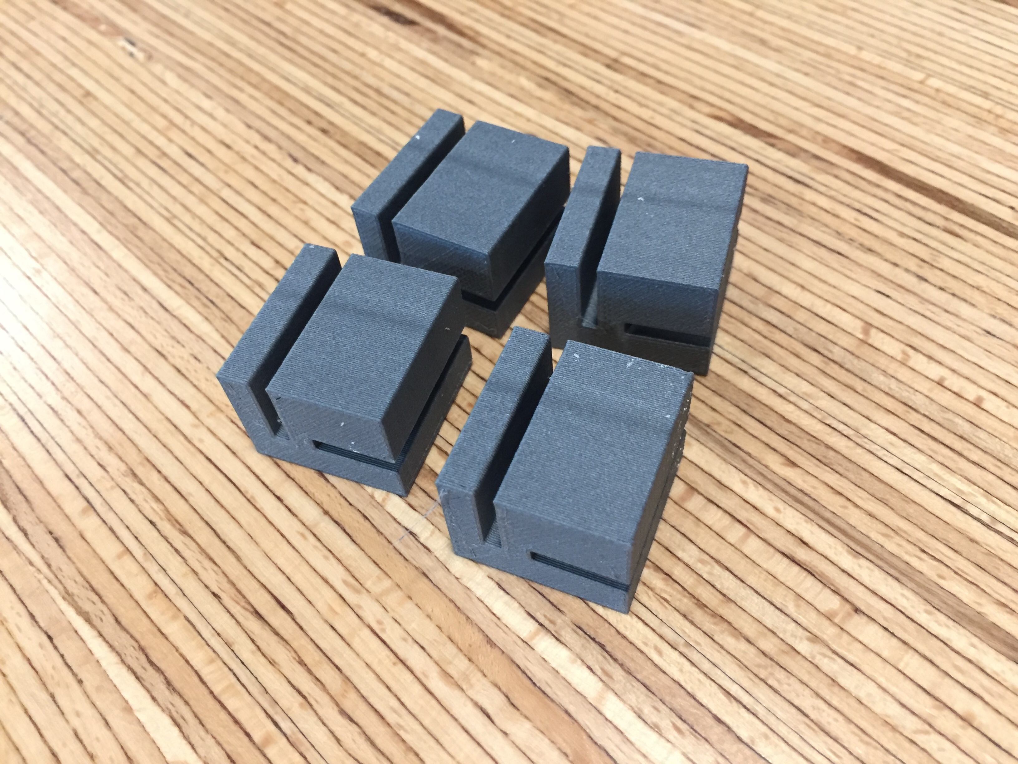
Test Print of a Top Connector

Top Connector Pieces
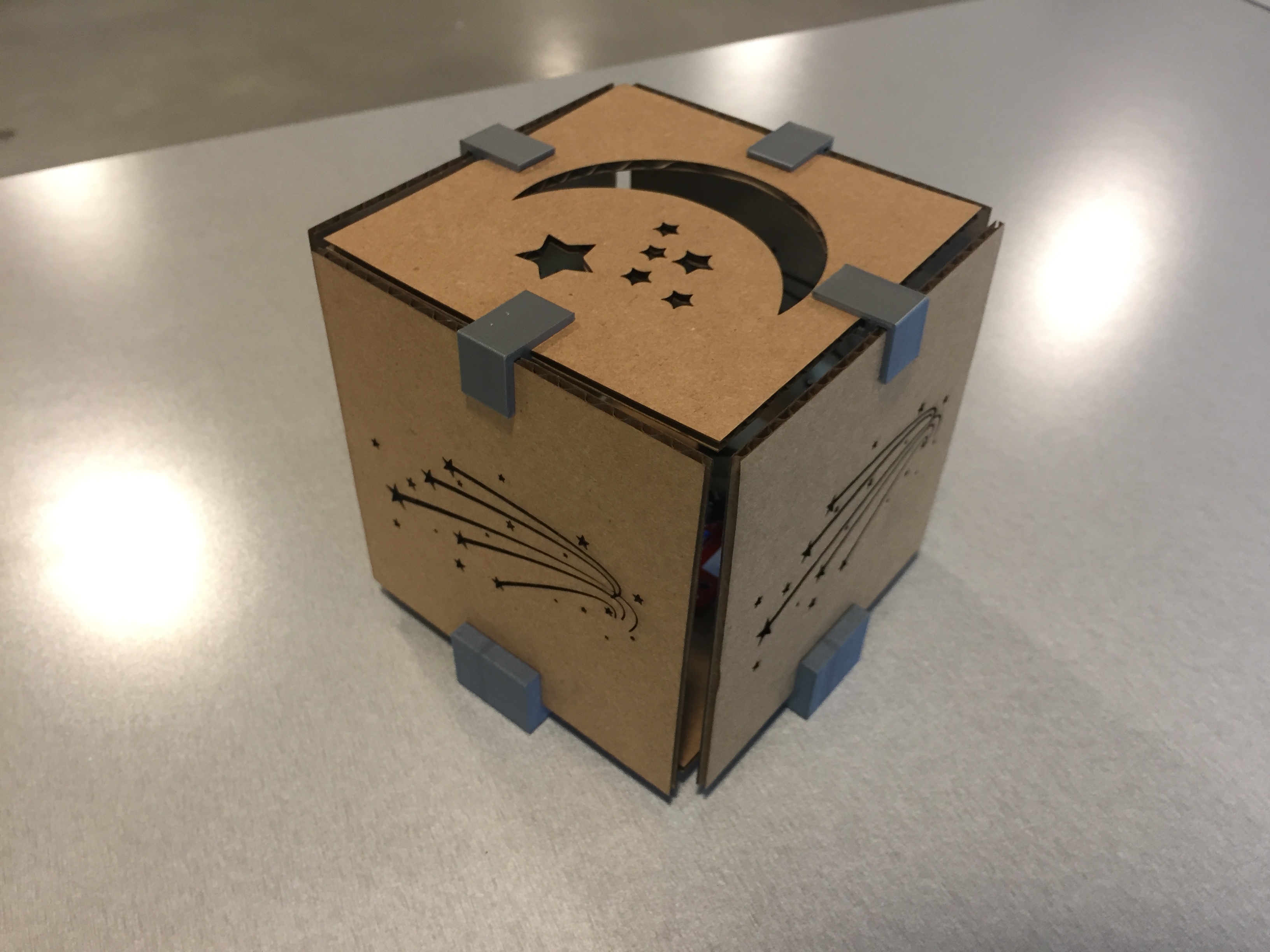
I chose to use Illustrator to create the panels since they were going to be in 2D, and I'm comfortable using Illustrator to make files for the laser cutter. My initial thought was to put a star on each panel, but I didn't want a huge hole in the middle of the panel. If I wanted to create an outline, I would have to think of a design where part of the star isn't cut so it can stay intact with the cardboard. I ended up doing a Google search on star vectors and found some shooting star vectors I liked that could still have a cool effect without producing a giant hole in the middle of the panel. I used image trace on Illustrator to outline each part of the image and ungrouped the image to remove the white background. I adjusted each shooting star or star to have no fill and to have a stroke of 0.001pt. I placed the image to where I wanted it to be located on the panel. Happy with how it looked, I went to the laser cutter to print out one panel to see how it looked. I was pleased with the test panel, so I went ahead and print out the remaining 3 middle panels. For the top panel, Kira gave me the idea to do a different pattern like a moon. I used a moon and star vector I found and did the same process of image tracing, ungrouping, and adjusting fill and stroke. I cut out the top panel and base panel (which is just a blank square piece) with the laser cutter.
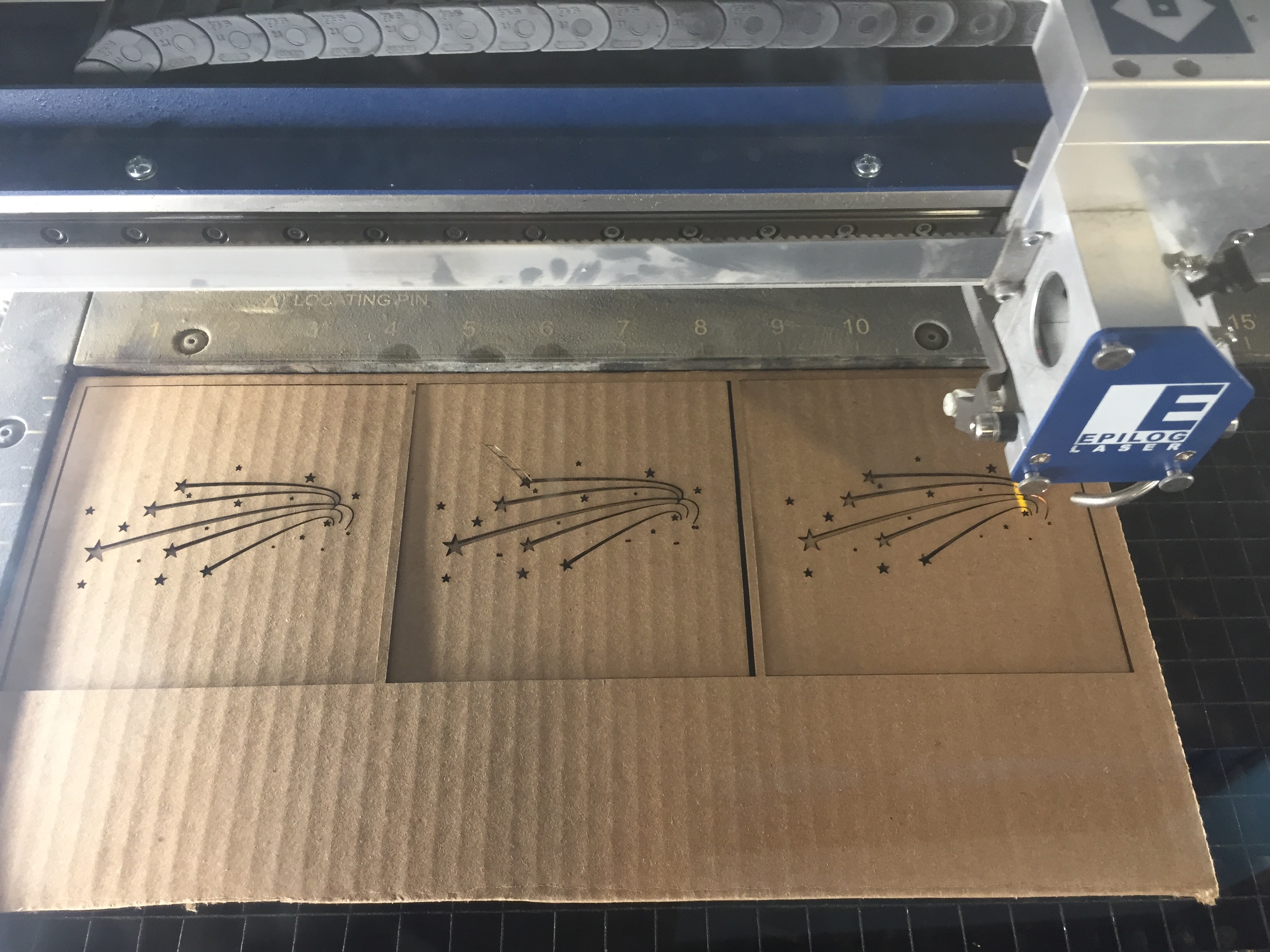
Laser Cutting the Panels
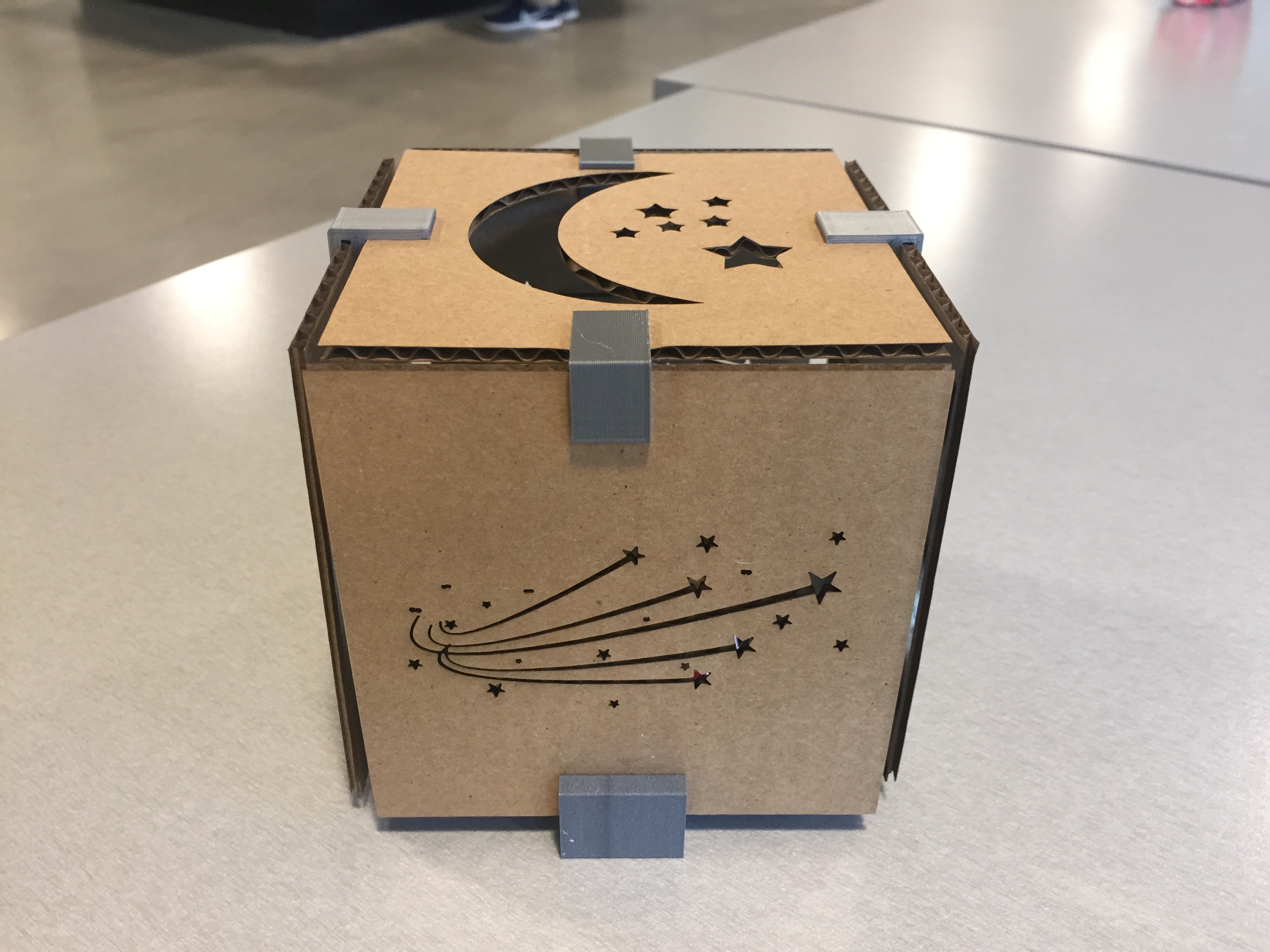
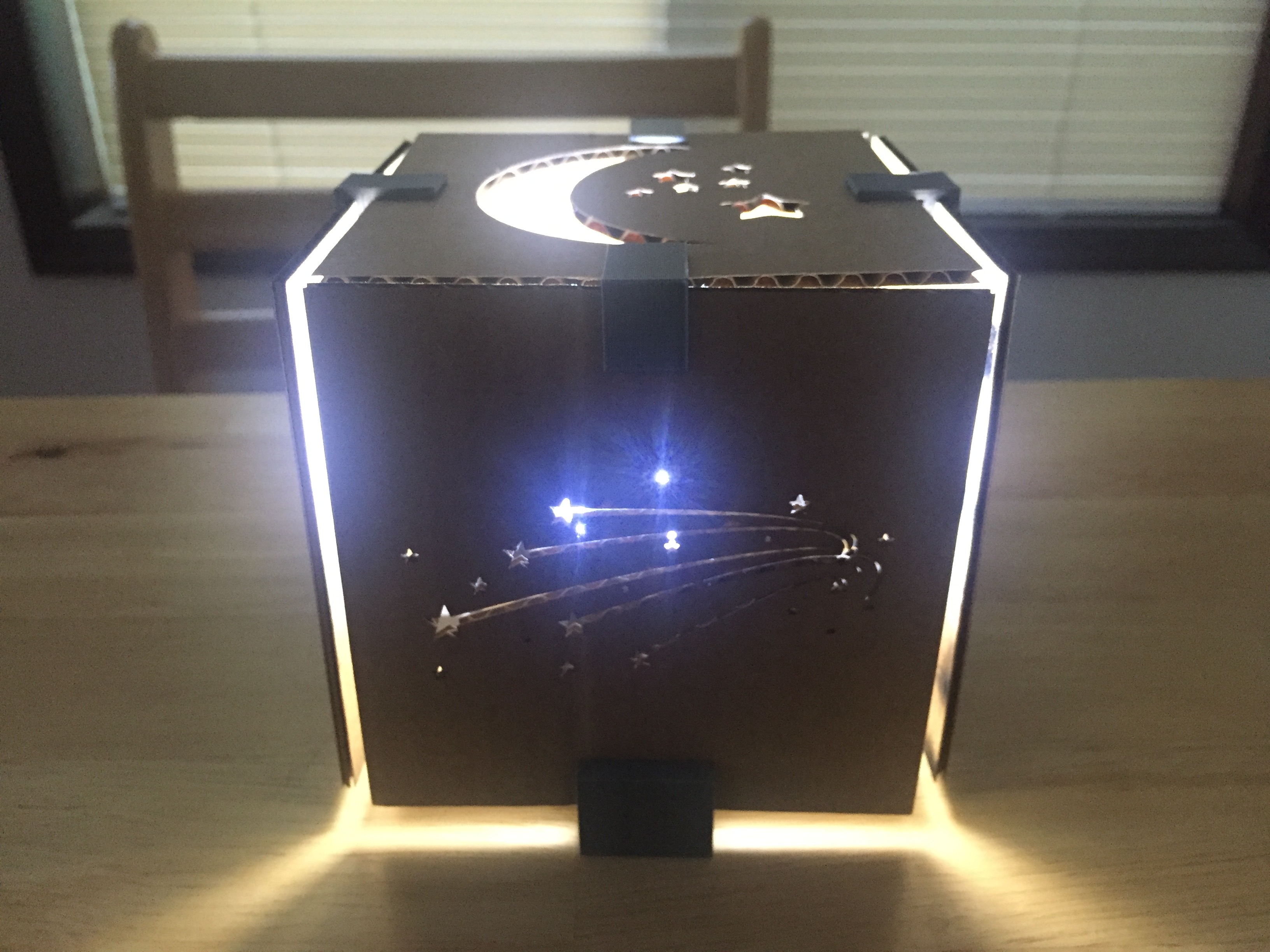
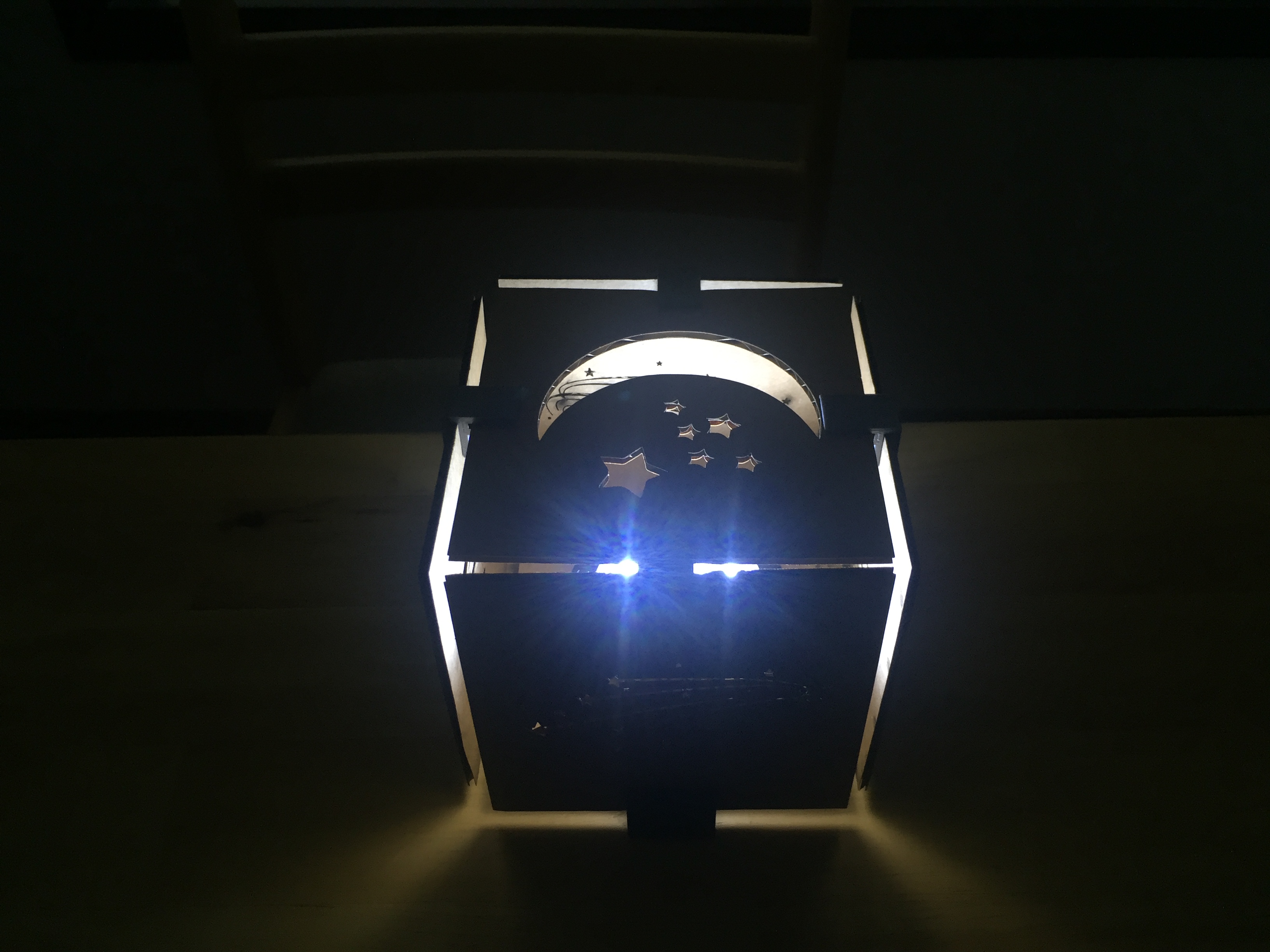
Now that I had all my connector pieces and my panels laser cut, it was time to put them together! And, ta-da! I'm proud of my finished product.
Peer Teaching: Joshua V for helping me with the export and 3D printing settings and showing me the alcohol trick to remove a 3D piece stuck to the glass plate
Creative Shoutouts: Elizabeth & Kira for giving me ideas I incorporated into the design
Vector Images:
Shooting Star Vector
&
Moon Vector