Hannah's Assignment 8: Final Project!

Polaroid Photo Stand & Storage Box (all in one)
Specifically for Fujifilm Instax Mini

Documentation and process are down below.


Concept


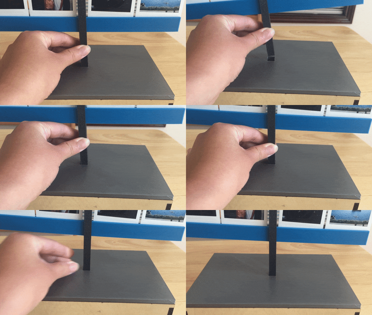
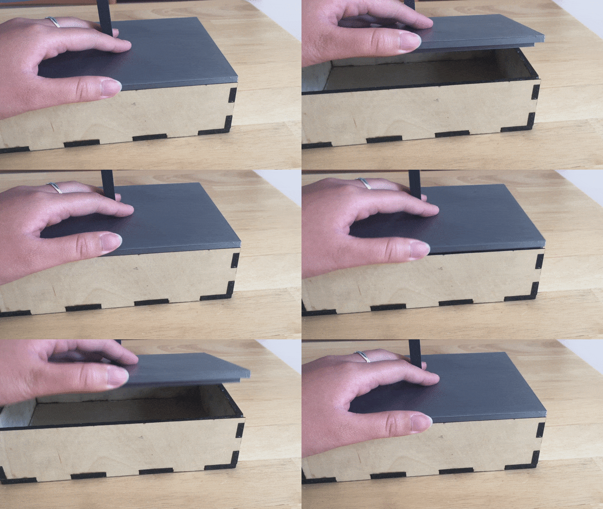
The polaroid photo stand and storage box is exactly what it sounds like. It is a one piece unit where you can display your polaroid photos and store the rest in the storage box. This idea was inspired by a huge stack of polaroids I have in my desk drawer. I specifically have Fujifilm Instax polaroids. The one unit would consist of a box, a pole that sits on the lid, and rods that go through the pole. The box design will have finger joints, so the box can easily fit together. The lid will have a semi-closed slot where the pole will sit. The pole will have two holes where each rod will go through. The rods have slots for the polaroid photos. This idea can be utilized as a home decor item. So if you have polaroid photos and want a way to display them, you can consider this option!
Design

Four techniques were used to execute this concept: CAD modeling on OnShape and Rhino, laser cutting, 3D printing, and interlocking parts. Components for this idea include a box, a lid, a center pole, and rods. I used CAD to design the entire piece. I used OnShape to create the box, center pole, and the rods, and I used Rhino to create the lid for the box. I chose Rhino for this part because of how comfortable I am with the program when it comes to boolean difference, boolean union and such. I used laser cutting to cut the box out of plywood. I used 3D printing for the lid, pole, and rods. Interlocking parts come into play with the fingerjoints on the box, the lid for the box, and where the rods intersect with the pole. Originally, I planned to 3D print clothespins from a file I found on Thingiverse. The clothespin would hold the polaroid and I would use twine to loop through the clothes pin and hang them from the rods. However, when I did a 3D print test of the clothespin for the sizing I wanted, it didn't work out. It was okay though because I had my backup idea! My backup idea was to create slots in the rod to stick the polaroids into.


Documentation

Source Files

OnShape Links: Box, Center Pole, Rod
Rhino files for Lid and Rod
STLs for 3D Printing
DXFs for Laser Cutting

Techniques

Bill of Materials

Dimensions

Machine Settings


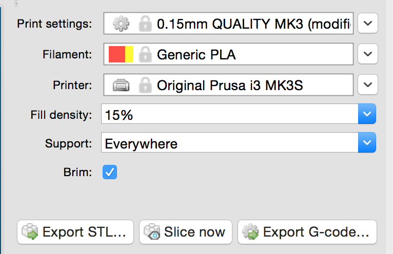
Prusa 3D Print Settings


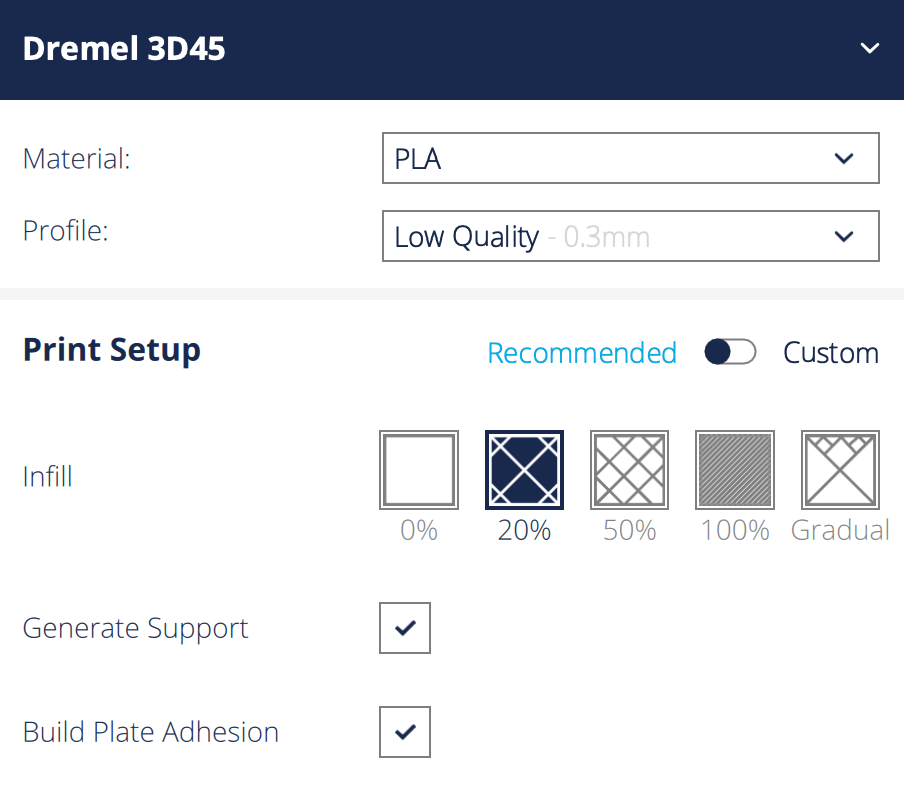
Dremel 3D Print Settings


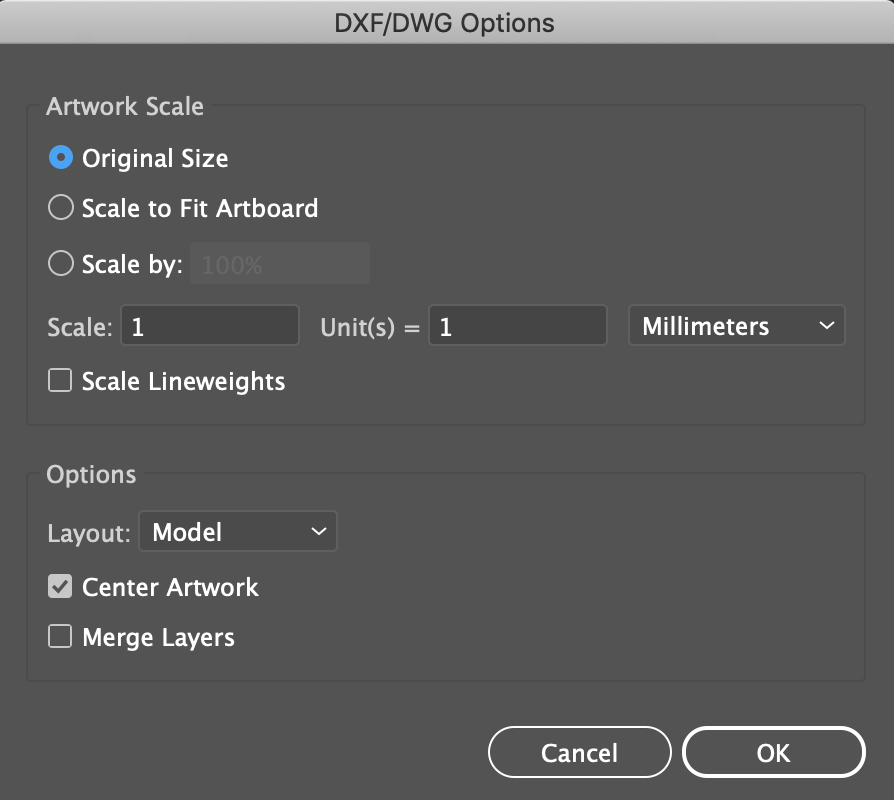
DXF to Illustrator Import Settings


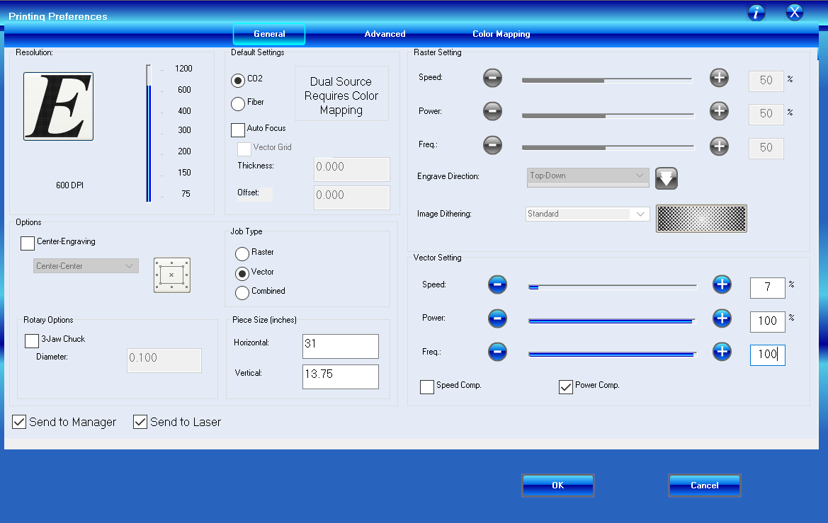
Laser Cutter Settings for Plywood


TL;DR how to execute this on your own

  1. Get materials
  2. You only need 2 materials to make the polaroid photo stand and box. These materials are listed in the Bill of Materials above.

  3. Download files
  4. Download the STL and DXF files if you want to make the stand and box exactly like mine. If you would like to make tweaks to the design, you can use the OnShape and Rhino files. I used millimeters as my unit for both OnShape and Rhino. For the rods, it's up to you which design you prefer - one overall slot across the rod or 1 slot per polaroid. Each rod holds 4 polaroids.

  5. Get access to machines
  6. You'll need a laser cutter and a 3D printer to execute the idea. The DXF files are for the laser cutter. If you open the DXF files with Adobe Illustrator, make sure to scale to original size, 1 to 1 mm. Applying masking tape to the plywood will help to avoid burn marks on the plywood. Since plywood will be cut, set the laser cutter speed settings low and power and frequency high.
    The STL files are for the 3D printer. Make sure you check the build volume of the 3D printer as the rods are the longest piece at 9-9.25". The poles and rods can be 3D printed at the same time on the same bed (again depending on build volume). Since the lid is one bigger piece, 3D print it on its own.

  7. Assemble pieces
  8. Once you have laser cut and 3D printed the pieces, it's time to put it all together! Once the pieces are assembled, you can put the polaroid photos into the slots and inside the storage box!


My Entire Creation Process

Step 1: CAD modeling box and lid
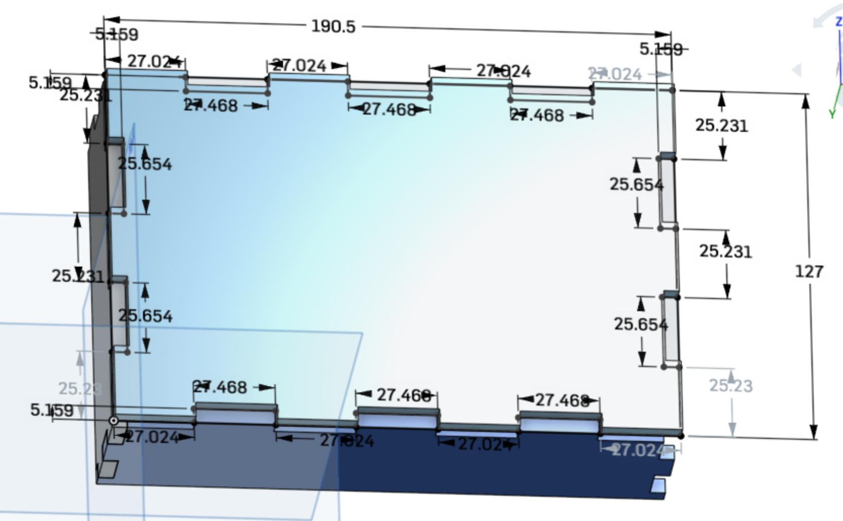
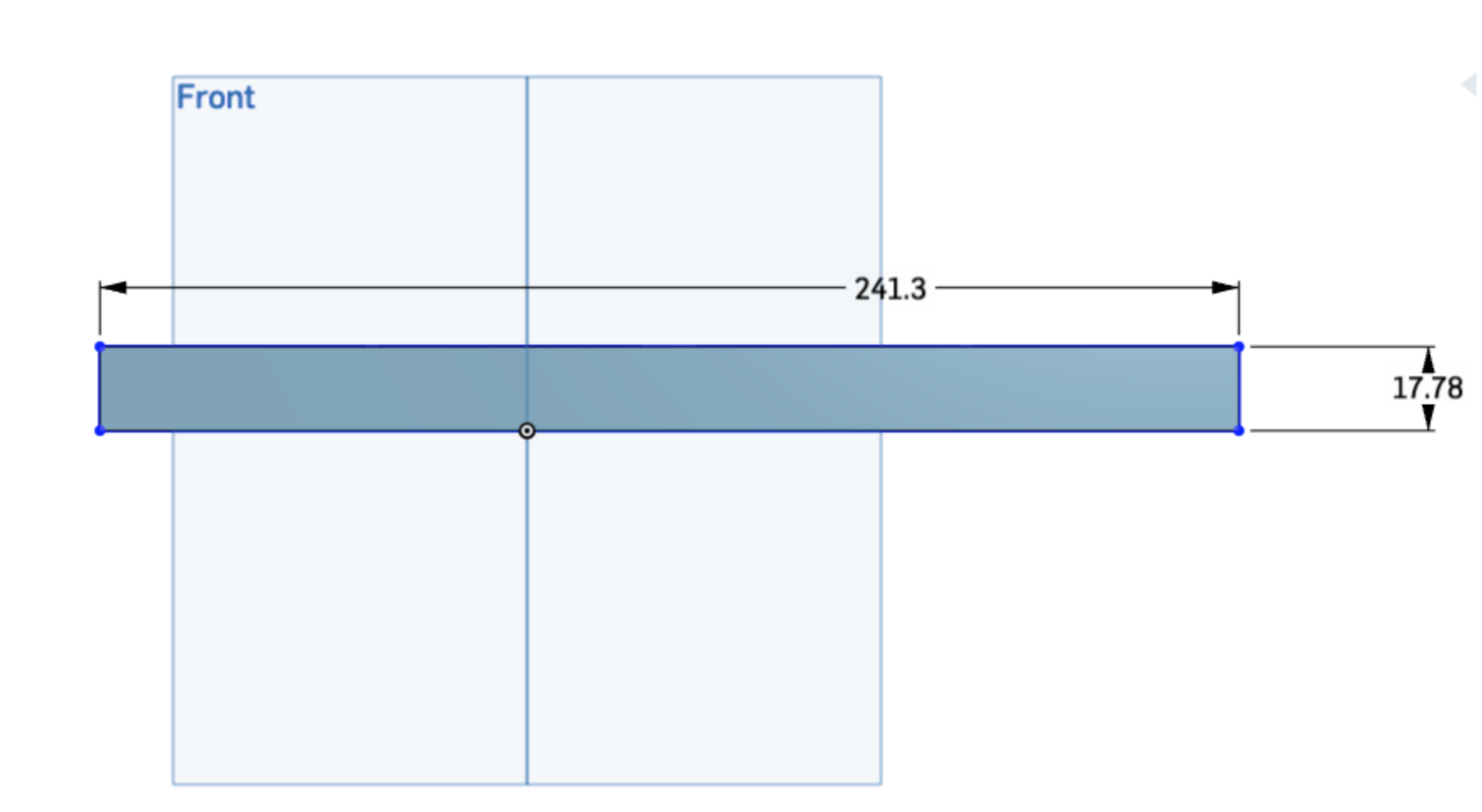
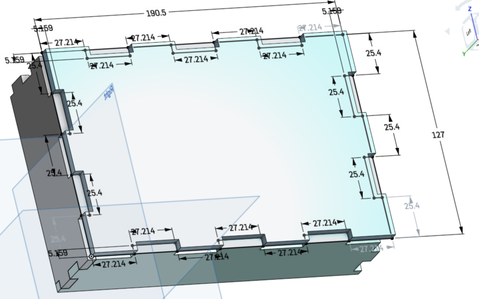
To kick off the whole process, I began with designing everything using CAD software. I started with the box (minus lid). I used OnShape to create a majority of the box. For me, OnShape is easier when creating pieces that need to be assembled together as well as making fingerjoint measurements as accurate as possible. I created the base of the box, the short side, and the longer side all in one document. The base of the box is 7" by 5". The short side is 5" by 2", and the longer side is 7" by 2". In my original design of the box, I made the female joints 0.01" bigger than the male joints. When I was done with creating each side, I extruded each sketch and then used the assembly feature on OnShape to see how the box would look like and to make sure the parts fit.


Units on OnShape and Rhino were in millimeters

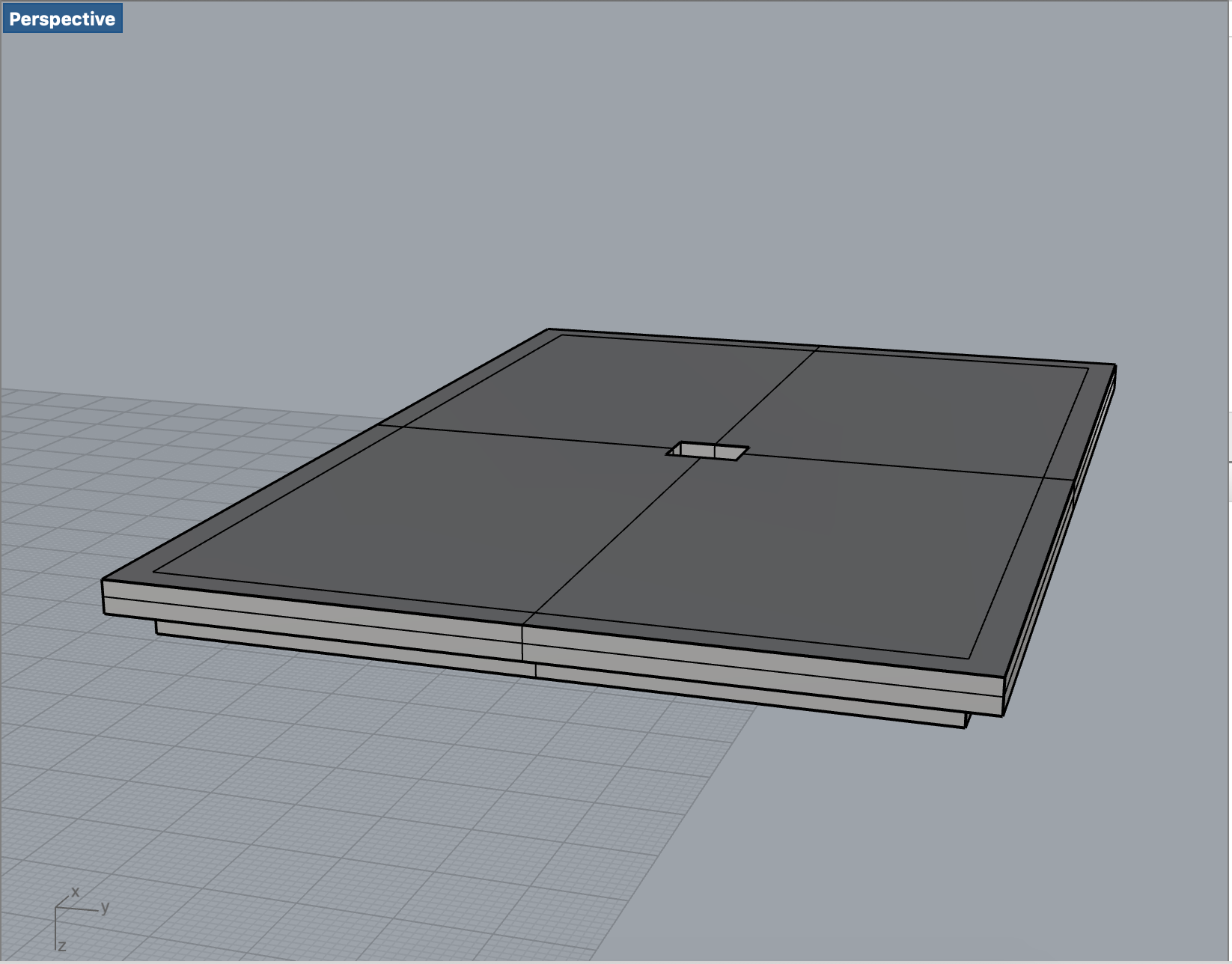
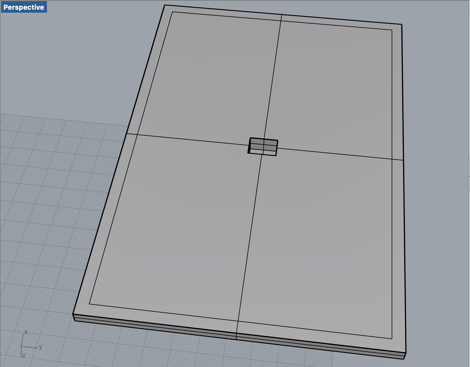
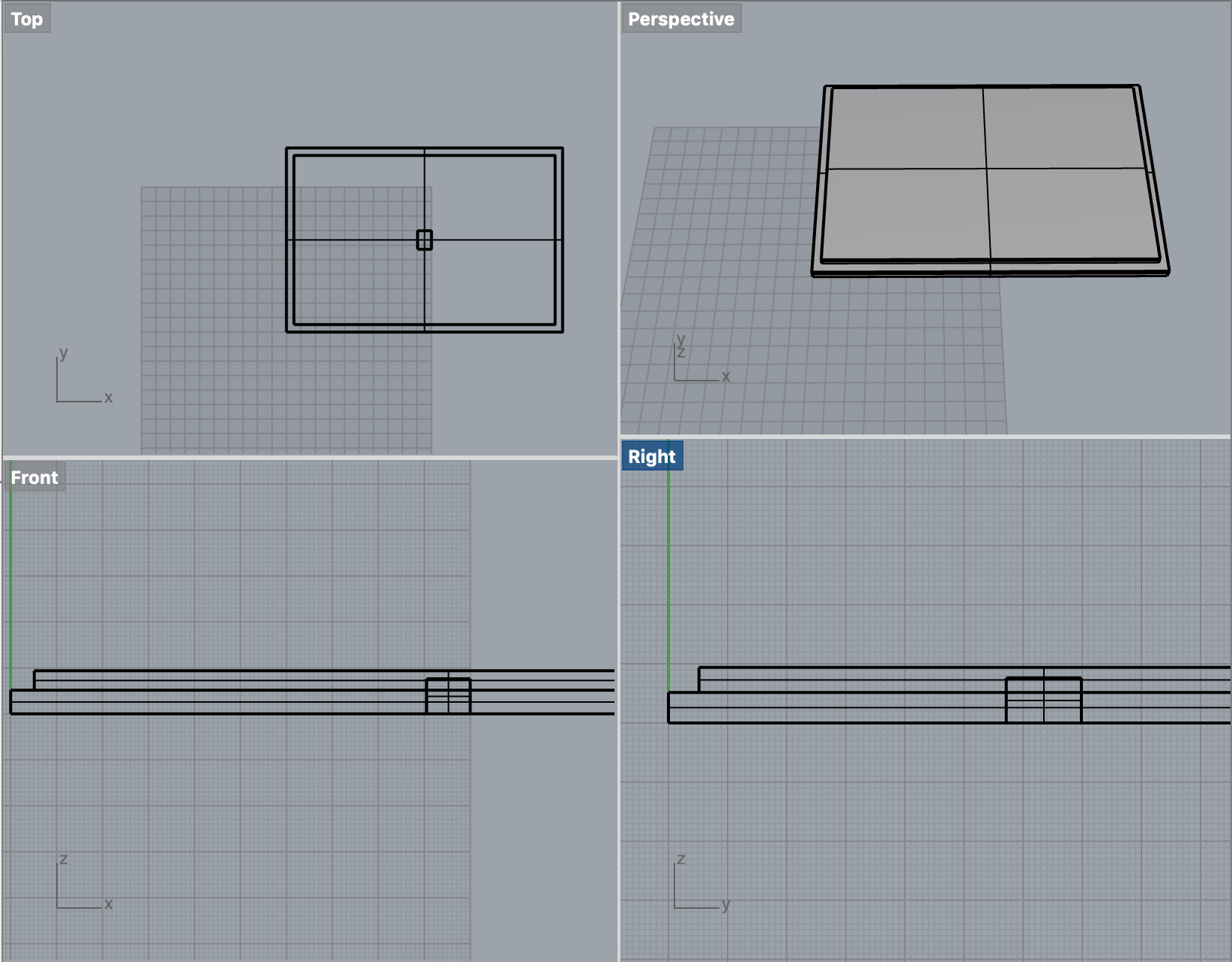
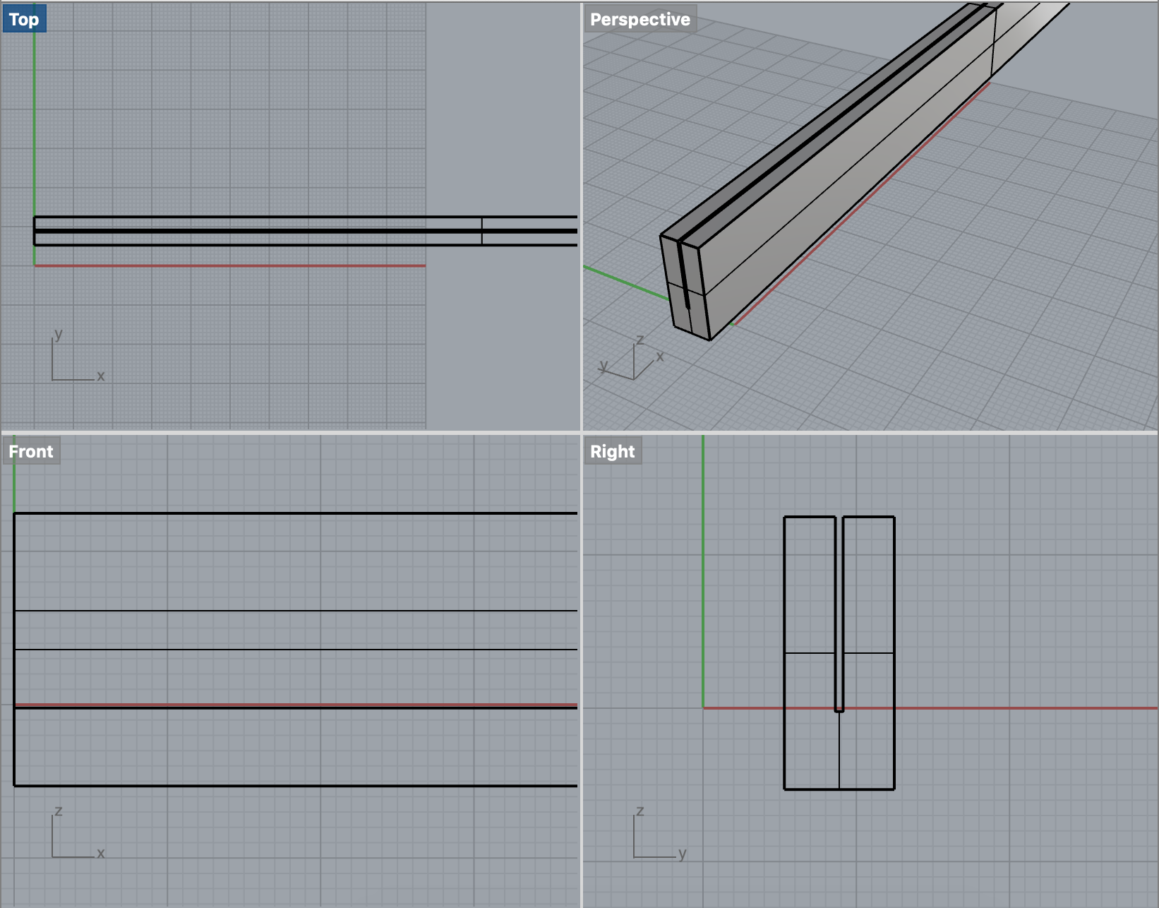
Once I was finished with the box, I went to Rhino to design the lid. As mentioned, I used Rhino because I'm more familiar with its boolean tools. I created 2 rectangles. One to be the top part of the lid (7" x 5") and one for the inner lip. I extruded the rectangles and capped them. I aligned the smaller rectangle to be completely centered in the larger rectangle. I moved the small rectangle box in the Z direction so it was resting on the bottom of the larger rectangle box. Using boolean union, I joined the 2 rectangular boxes together. Then I created a tiny rectangle for the slot that is meant to be on the top of the lid. This is where the pole is to be placed. I extruded and capped the tiny rectangle, placed it in the center of the top of the lid, and used boolean difference to make the slot.

The last things I had to design on CAD were the pole and the rods. However before designing them, I needed to test out my clothespin idea.

Step 2: Testing out clothespin idea
As mentioned in my proposal, I had a design idea of using clothespins to hold the polaroids and using twine to hang the clothespins from the rods kind of like a jewelry stand. However, I wasn't sure how executable this idea was. I found a clothespin STL file on Thingiverse that had a spring that can be 3D printed. The issues were that I needed to resize the clothespin to make them much smaller and to add holes to the top of the pegs, so twine can go through. When I resized the clothespin and added the hole, I did a 3D print test. The 3D print didn't turn out, and I didn't want to spend too much time adjusting and readjusting to make the idea work. Additionally I needed the clothespins to be tiny because of the limited height of the pole due to 3D printer build volume constraints. I already knew the dimensions of a polaroid and to leave extra room and build within build volume constraints, the clothespins just weren't going to cut it. Fortunately, I had a backup idea! Inspired by the connector pieces I made for the lamp assignment, I decided to make rods that had slots, so the polaroids can slide into them and be displayed that way.

Step 3: 3D printing the lid
After my test clothespin 3D print, I went ahead and started the 3D print for the lid. Fortunately, I didn't have to make adjustments as the clothespin is separately designed from the box. I used a Prusa 3D printer for the lid. I sliced the file using Slic3r and put the gcode into an SD card. I put the SD card into an available Prusa printer and started the print! A CoMotion staff member helped me get started by cleaning the platform and showing me how to use the printer.

The print took 7.5 hours, but it was a success! I picked up my print from Fluke CoMotion the next day.

Step 4: CAD modeling
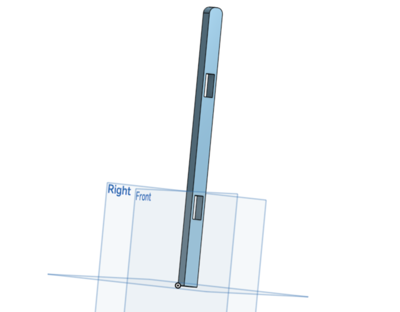
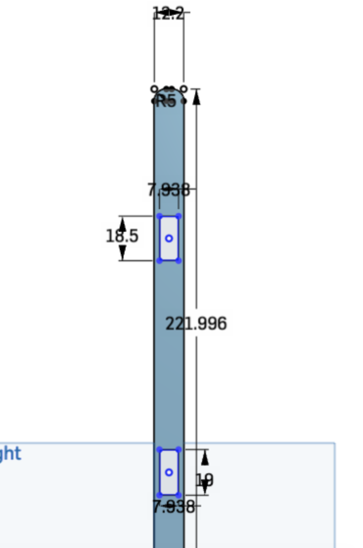
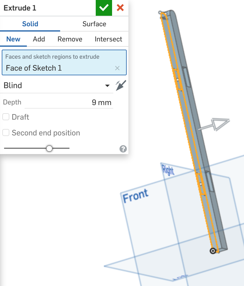
After I started the 3D printing process for the lid of the box, it was time to continue working on CAD for the pole and rods. As I mentioned, my clothespin print test didn't work out as expected, so I decided to go with my backup plan to alleviate stress from perfecting one idea. For the backup plan, I needed to design the rods so they would have slots that the polaroid can slide into and will hold up the polaroids. The pole would need two holes for the rods to slide into, and the placement of the holes also need the right spacing between them for the polaroids to be displayed nicely. I first started with the design of the pole. Knowing my build volume constraint of the 3D printer and the size of a Fujifilm instax mini polaroid, I chose the height of the pole to be 8.75". I chose this to allow space for 2 rows of polaroids to be displayed and still have room between the bottom rod and the lid of the box. I used OnShape to design the pole. The thickness of the pole was based on the size of the slot I made on the lid which was .5" x .4". Having tolerance in mind I made the pole .01" smaller than the slot. Knowing the width of the pole, I was able to determine the width and height of the hole (.31" x .75"). I chose .75" because the bottom portion of the polaroid is .62", so I wanted to make the slot for the rods .5". I spaced the holes a little over 3" apart, so the polaroids in the bottom row can sit comfortable without hitting the upper rod.

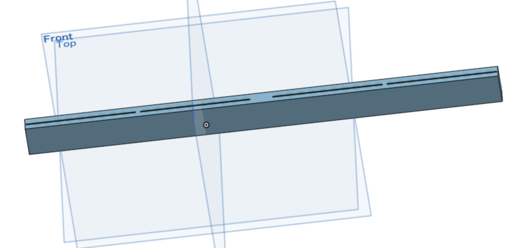
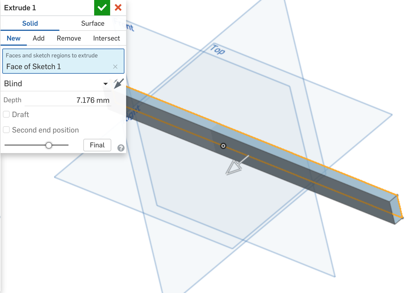
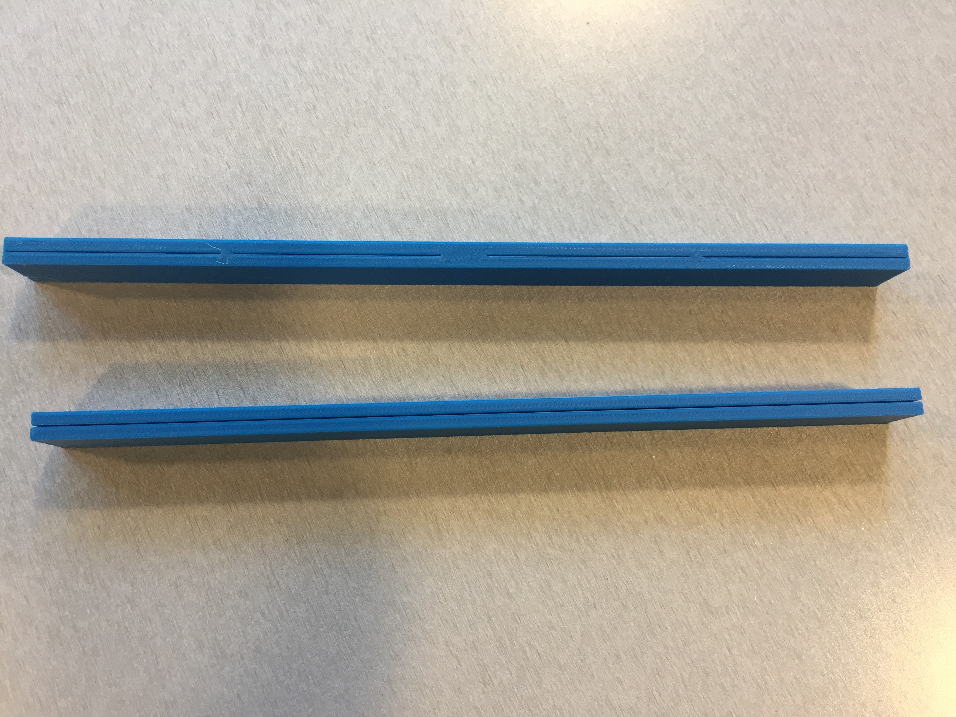
Once I was done designing the pole, I designed two types of rods. I designed one rod on OnShape and one on Rhino. I designed two types because I wasn't sure how I wanted the slots to be on the rod. One rod had just one slot across the length of the rod, and the other had 4 slots created - 1 slot 1 polaroid. I made the rod with the one overall slot on Rhino because of its design simplicity and ease of use of the tools I needed (rectangle, extrusion, cap, boolean difference). I made the other rod on OnShape to utilize the linear translate tool to evenly space the 4 slots and to have more control moving and aligning extrusions and such. The one overall slot rod on Rhino is 9" wide with a slot of .51" (thickness of polaroid). In hindsight, I would've made the slot a little wider for the polaroids to go in more easily. I made the 4 slot rod a little longer to get spacing between slots and to have proper spacing in the center for where the rod and pole intersect. Initially I made the extrusion and height of the rods .01 in smaller than the hole due to tolerance.


Step 5: 3D printing the pole and rods
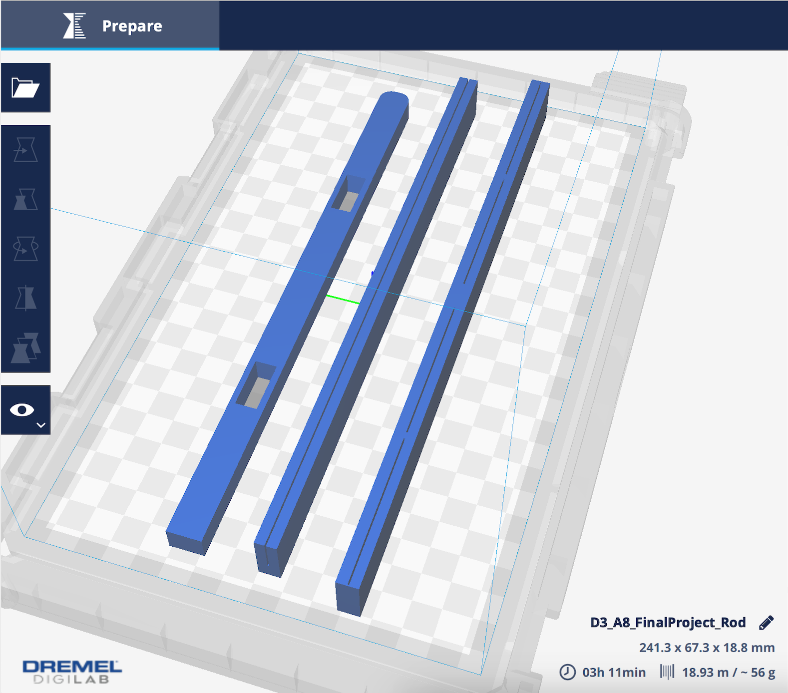
Once the CAD files for the pole and each version of the rods were ready, I exported them into STL files. For the OnShape CAD files, I exported them into Rhino first then to STL due to a weird sizing issue that happens when I export into an STL file straight away from OnShape. I opened all the STL files with DigiLab to have them print in one sitting. This time I used the Dremel Digilab printer as I prefer the more flexible hours of the MILL. I sliced the file and saved it to a USB, found an open printer, and started the printing process. A few hours later, the print was done.


Step 5b: Challenges and adjustments
Once I scraped the pieces off of the 3D printer platform, I tested out the pieces to make sure they fit together. However, the rods were not able to slide into the holes of the pole as they were a little too big. Even though I had included tolerance into my design, I needed a higher tolerance in order for the rods to slide through. With Lukas' help of measuring the hole sizes of the printed pole with calipers, I readjusted the sizes of the rods to be slightly smaller. I also had to readjust the thickness of the pole due to the same issue of it not fitting into the slot of the lid. The .01" tolerance wasn't enough. I used the same process of measuring the slot hole with calipers and adjusting the thickness of the pole to be slightly smaller, so that it would fit.


Once I made the adjustments, I reprinted each piece, and this time around it was successful! The rods fit into the holes in the pole and the pole fit into the lid! I ended up using both version of the rods I made cause I liked how each turned out and wanted to play around with each for the final assembly.

Step 6: Laser cutting the box
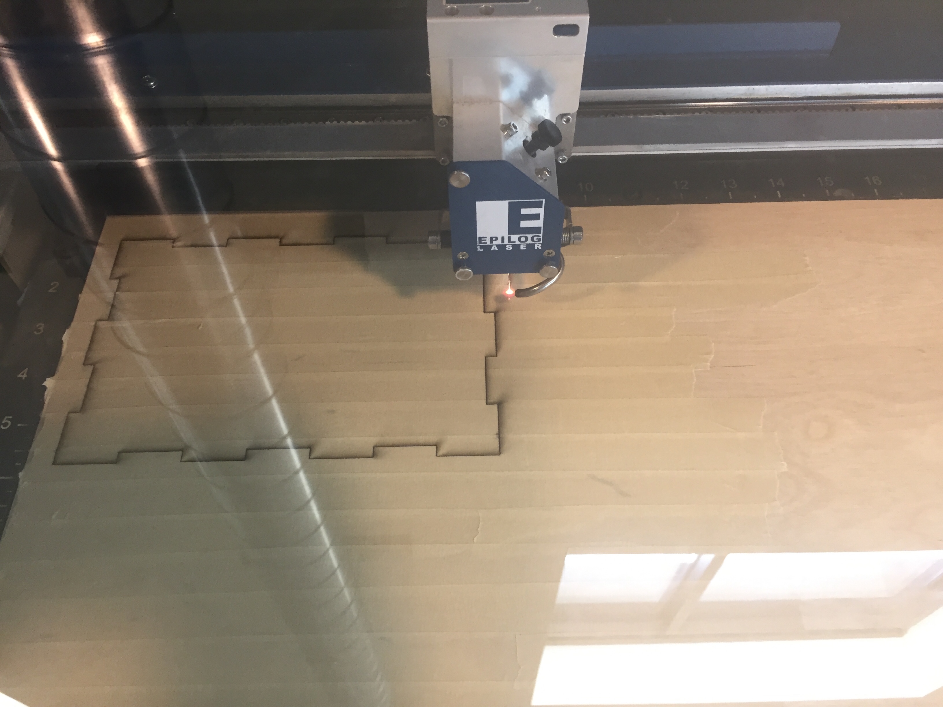
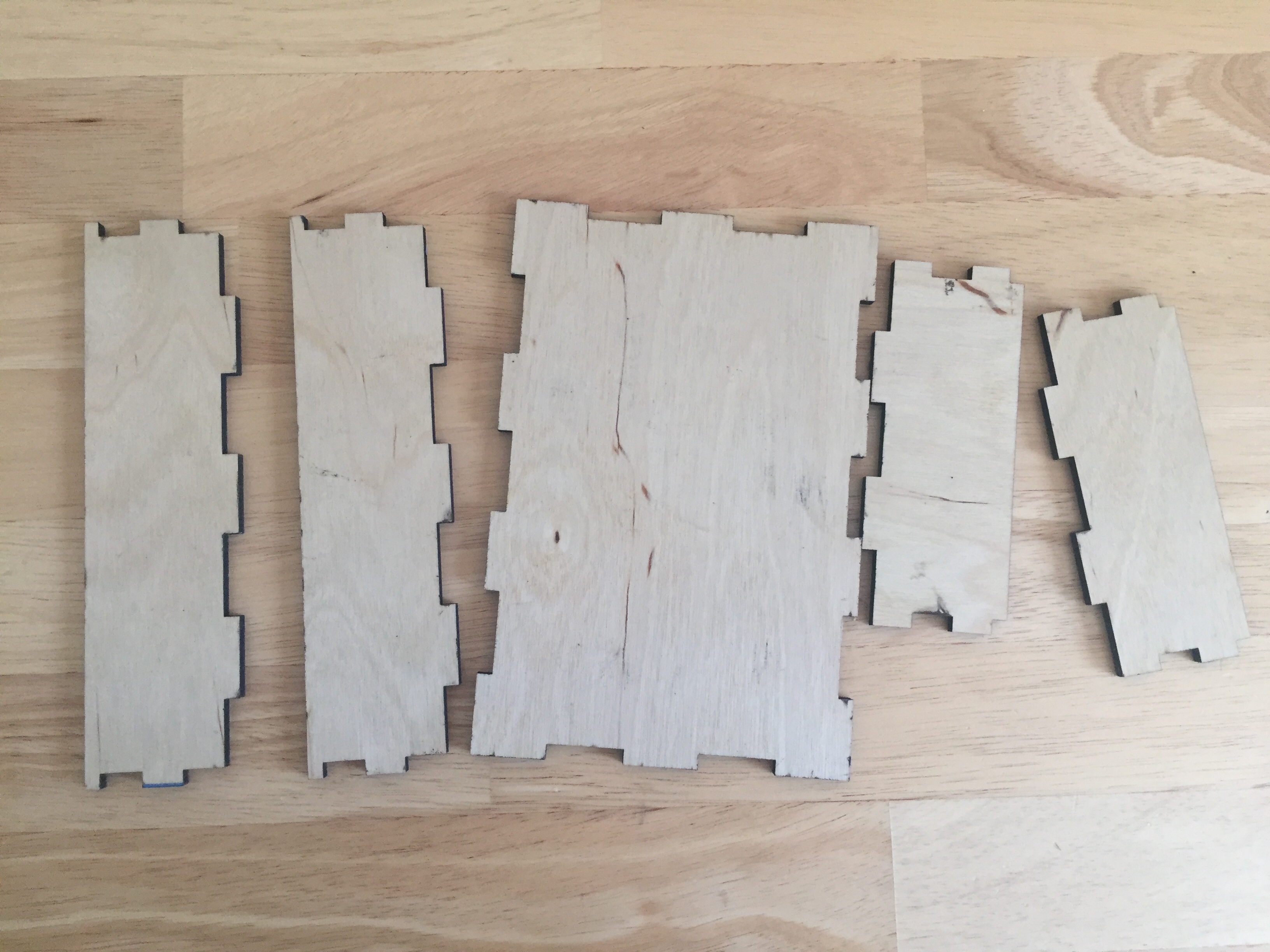
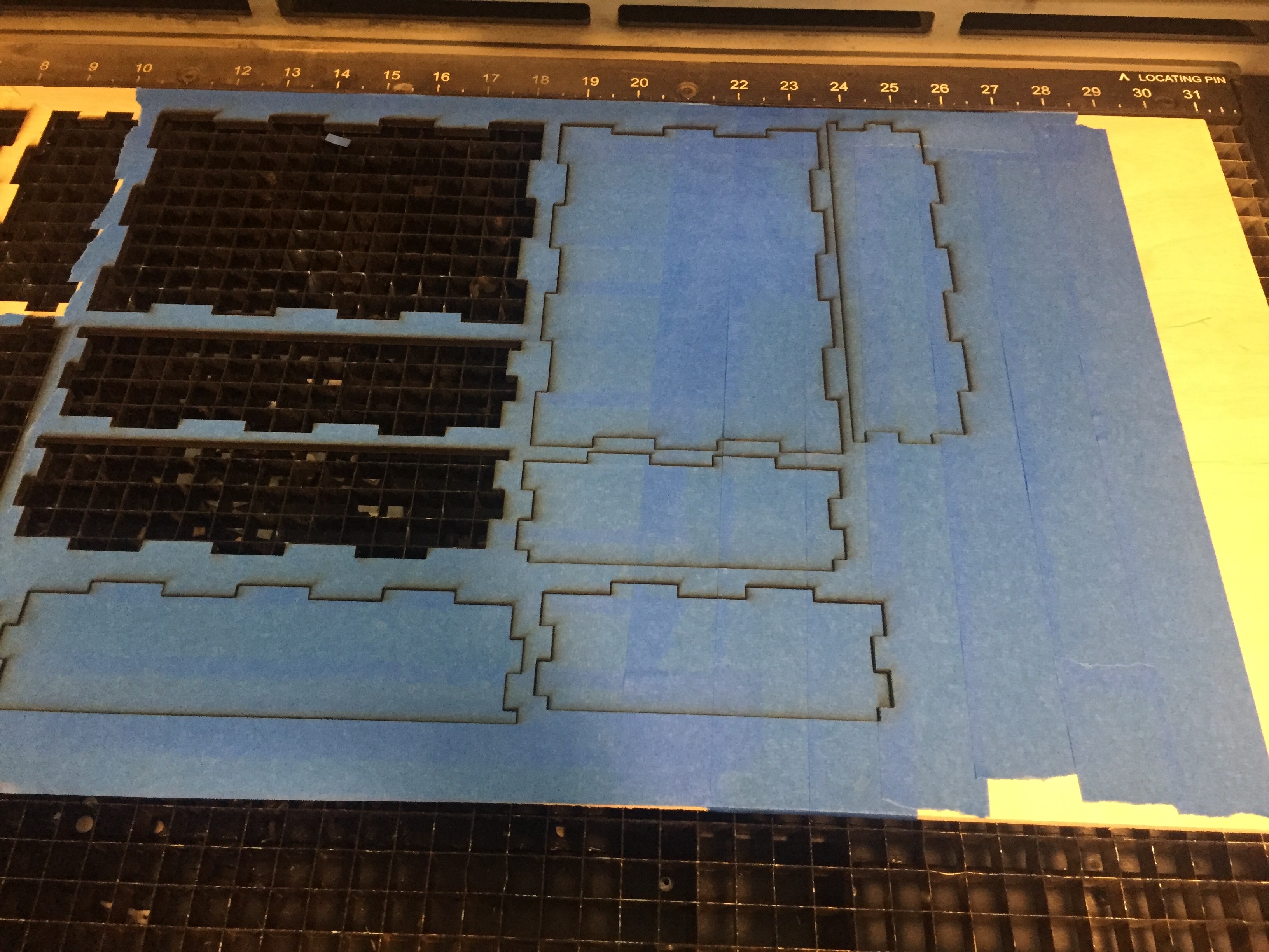
The last process was laser cutting the box. As mentioned it was the first thing I designed, but I didn't laser cut until towards the end. I exported each side to a DXF file and then opened each file on Illustrator. I chose to do a test cut first. I put all sides into one Illustrator file and when the file was ready, I went to the laser cutter, adjusted the focus, and set up the cutter settings. The test print showed me that the original tolerances I had made the pices not fit together super tightly. Lukas helped me adjust the male and female fingerjoints. I originally chose .01" because of how I made the box for the milling asignment. This time Lukas suggested .003" which is what I did and readjusted my OnShape file, re-exported, and re-cut. When I was ready to do a cut on the plywood I bought, I exported the files and redid the whole process of setting up the file on illustrator and setting up the laser cutter. I also applied masking tape to the plywood, so that burn marks don't appear on the plywood itself.

Step 6b: Challenges and adjustments
I still had issues with the updated fingerjoint file and tried out .001" tolerance when the .003" tolerance didn't work. Elizabeth was the one who suggested to me that the tolerance offset was to be applied to the entire file. What I ended up doing was making the male and female fingerjoints the same size and then in Illustrator set up an offset of .003" as mentioned in class.

Once I made the adjustments, I went back to the laser cutter and followed the same laser cutitng process.

Step 7: Assembly!
Now that I had all the pieces ready, it was assembly time! I put the plywood box together, placed the lid on top, placed the rods through the pole, and put the pole into the slot in the lid. Once all the pieces were assembled, I just needed to put the polaroids in! I'm pleased with how it all turned out!

Snippets of the Process


Back to main page